You are here: CSP Developer’s Guide: Common Channel Signaling > 8 ISDN > ISDN Call Processing

Overview
Understanding the various phases of the call makes it easier for you to manage the events and information flow. This section describes the call phases and events and identifies what you must do to use the call processing capabilities. This section also describes the level of control for call processing that you must engineer. The topics in this section include:
• Incoming Calls
• Outgoing Calls
• Releasing Calls
• Overlap Receiving
• Overlap Sending
Before you begin
Before you continue, make sure the following have occurred:
• System configuration is complete
• Spans are framed
• All D channels are established
• All B channels are in service
The Outseize Instruction List Configure message is not supported for ISDN PRI. All outseize instructions must be sent in the Outseize Control message.
Perform all PPL configuration after you specify the variant with the ISDN Interface Configure message.
Incoming Calls
An incoming call is indicated by a SETUP message containing IEs to describe the span, channel, bearer capability, called and calling party, and services requested. The CSP validates and verifies the information based upon the ISDN PRI variant and, if successful, returns a CALL PROCEEDING or SETUP ACK. A SETUP ACK returns if the ISDN PRI variant is set to Euro-ISDN (0x07) or Euro-ISDN Netside (0x17), and the overlap receiving mode is enabled. Otherwise, only the CALL PROCEEDING returns from the CSP.
Normally, only the span, channel, called and calling party are needed for most applications. This is provided in the Request for Service with Data message using the default BCD Encoded Stages format. This is the same message, common across the CSP, that reports the called and calling party address digits.
Important! The Inseize Control and Inseize Instruction List Configure messages are not supported for ISDN PRI.
If access to all IEs is required, configure the Request for Service Format to Formatted ICB. Formatted IEs reformats the most used IEs to a byte-oriented format which is easier to parse. This abstracts the ISDN specifics from the host to provide what is necessary, in a generic form. IEs that are not supported in the formatted mode are sent to the host in the Raw IE ICB.
The Request For Service Format is configured with Config Byte 1 of the L3P Call Control PPL Component (0x05). The following options are configurable:
• BCD Encoded Digits (0x01)
• Formatted ICB (0x03)
• Exact Frame (0x04) - (host must parse)
At this point in the call, the network is waiting for a CONNECT message. Prior to this, an ALERTING or PROGRESS message informs the network that the CSP is awaiting answer on the B party of the CSP. One method of sending the ALERTING message to the network is to send a Park Channel message for the incoming span/channel. This disables Layer 4 timers for the call.
Normally, the host attempts an outgoing call (Outseize Control) to connect to this incoming call. If a Connect message is sent to the CSP after a successful seizure, the answer propagates to the incoming side (CONNECT) assuming the Answer Supervision Mode Configure message is set to Propagate Answer To Distant End (default).
To automatically answer an incoming call, send the Generate Call Processing Event of answer, which sends an ALERTING followed by a CONNECT. This puts the call in an answered state and incoming billing is started.
Call Flows for Incoming Calls
Incoming ISDN Call to Outgoing ISDN Call
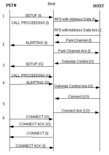
The following call flow shows an incoming ISDN call (I) from the network. For this application, another ISDN call (O) is generated on a different span/channel combination.
1. Upon receiving the SETUP from the CO, the IEs are validated and the CALL PROCEEDING is automatically returned. The SETUP is transformed into the Request for Service with Address Data and sent to the host.
2. The host parks the channel, which causes the ALERTING message to be sent for that call.
3. The Outseize Control message is sent to originate a call. For the common API approach the instructions should be:
• Seize
• Send Host ACK
• Wait for Host Control
• Data: Stage 1 Digits
4. Upon the reception of the ALERTING or PROGRESS, the Outseize Control ACK is returned to the host.
5. To establish a 2-way circuit switched connection between the channels, the host issues a Connect message.
6. Once the outgoing call is answered, the connect is propagated to the incoming side only if the answer supervision is configured to be "propagated." See the Answer Supervision Configure message.
Incoming ISDN Call to an IVR (Interactive Voice Response)
The following call flow shows an incoming ISDN call with a seize and connection to an IVR port with a trunk type of E&M Wink Start.
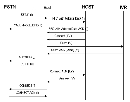
1. The host sends a Connect or Connect with Data message to force the second span/channel combination to seize and then gets connected to the incoming call. Use this message to seize the second party if the trunk type does not require digit outpulsing. ISDN outgoing calls must have the Called Party specified in the Outseize Control message. The connect messages cannot be used to originate an ISDN call.
2. Assuming that the IVR is configured to the trunk type E&M Wink Start when the wink has returned the ALERTING message is propagated to the incoming side and has the Information Elements (IE), if any, passed in the Connect with Data message. Detecting the outseize ACK (wink) also causes the circuit switched connection to occur.
3. Sometime later the IVR answers, which propagates the CONNECT to the ISDN.
Incoming ISDN Call Answered and Parked
The host can send a Generate Call Processing Event of "answer" to generate the appropriate ISDN signaling to the network. The CSP will park the call in this scenario and the incoming caller will hear silence until reconnected or tones/announcements are played.
Sending Outgoing Calls
To send a Setup to the network, use the Outseize Control message. The easiest method to use for inserting called and calling party digits is to use the Stage N Address Data ICB. All other necessary ISDN specific information derives from the configured options of the B Channel Configure message. Information, such as number types and plans, is preconfigured using this message.
For call-by-call service selection, send the Outseize Control message using the ISDN Formatted IEs and ISDN Raw IEs ICBs, which is the recommended method. When doing this, specify the number type and plan for the called party IE and the calling party IE. You can also specify other IEs to be inserted.
Several IEs are inserted in the outgoing SETUP automatically:
• The ISDN header (protocol discriminator, call reference and message type)
• The Channel Identification IE
• Bearer Capability IE
• Any IEs configured and implemented in the PPL
The B channel configuration options are interpreted and inserted automatically if not represented in the Outseize Control message (see the section on B Channel Configuration for the table). Inserting IEs in the Outseize Control message override the configured values and are inserted in the SETUP.
Once the SETUP is sent, the CSP waits for a CALL PROCEEDING ACK, or a SETUP ACK. Once the ALERTING, PROGRESS, or CONNECT occurs, the Outseize Control ACK returns to the host. You can send each of these events to the host with the data included using the PPL Event Indication message. Once the ACK is sent, the host performs any of the Layer 4 specific call processing events.
When the CSP receives no response from the network
If the CSP does not receive a network response to the SETUP in eight seconds, it responds to the host Outseize Control message with a state of Outseize Failed, No Answer (0x1B). Eight seconds is two full cycles of the Q.931 Timer 305, which is L3 Call Control PPL Timer 5 and has a default value of four seconds. The SETUP is rejected by L3 if any IEs are invalid or missing.
The CSP responds to the host Outseize Control message with a status of 0x17 (Invalid Data Type). The L3P Call Control PPL sends an ACK to the host for an Outseize Control message. The default PPL does not examine the Send Host ACK ICB (0x08) in the Outseize Control message.
If involved in a tandem connection, reception of the ALERTING, PROGRESS, or CONNECT causes the voice path to get cut through. This is controlled by changing the PPLs.
In the case of distant-end release (as a result of the Outseize Control), if the called party is busy, a DISCONNECT or RELEASE COMPLETE is sent to the CSP and a PPL Event Indication is sent to the host with the Cause IE indicating the reason.
Important! Outseize options are configurable by modifying the PPL configuration bytes of the L3P Call Control component (ID 0x05). You must modify the config bytes to enable the following options:
– Config. Byte 11 (Euro ISDN/Austel only): Send a SETUP ACK and PPL Event Indication of More Info to the host upon receipt of SETUP ACK from the network.
– Config. Byte 12: Send a PPL Event Indication of Call Proceeding to the host upon receipt of a CALL PROCEEDING indication from the network.
– Config. Byte 13 (Euro ISDN/Austel only): Send an Outseize Control ACK to the host upon receipt of a SETUP ACK from the network.
– Config. Byte 14: Send an Outseize Control ACK to the host upon receipt of a CALL PROCEEDING message from the network.
Call Flows for Outgoing Calls
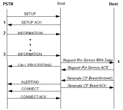
Outgoing ISDN Call with Raw Formatted Data Call Processing Events
The following call flow shows an outgoing ISDN call with the PPL Event Indication bytes set to report each event. Upon reception of one of these messages, if configured it gets reported to the host. This assumes that the Outseize Control message has the following instructions:
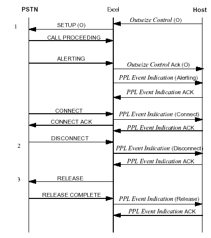
1. Seize
2. Send Host ACK
3. Wait for Host control
4. Data: Stage 1 Digits
5. The Host ACK is sent as soon as the CSP validates the Outseize Control.
6. All of the ISDN messages after the SETUP can be sent to the host in a PPL Event Indication message. The Information Elements (IE) are parsed and certain IEs are put into the message to the host depending on the message type (see PPL Event Indication 0x43 in the API Reference).
The DISCONNECT IEs could be reported to the host, as shown here in a PPL Event Indication message.
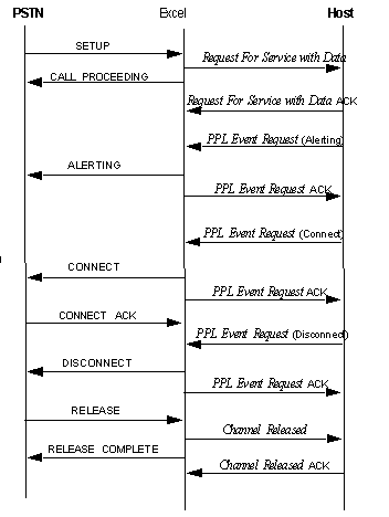
Incoming ISDN Call with Host Control of Call Setup and Release
The following call flow and all optional information elements to be included with each ISDN message. You can include optional IEs with any of the PPL Event Request host messages. These IEs are validated and then issued with the ISDN message. The ISDN PPLs ensure that the mandatory IEs are included with each ISDN message.
Releasing Calls
You can release a call in the following ways:
Network-Initiated
For a network-initiated release, a DISCONNECT is received. If the appropriate PPL configuration byte is set, release is reported to the host in a PPL Event Indication message. It could be parsed for access to the IEs by the application. By default, the CSP returns the RELEASE message and once the RELEASE COMPLETE is received the CSP sends the Channel Released message to the host.
Release Channel or Release with Data messages
For host-initiated release, send either the Release Channel or the Release with Data message. If not specified, the Normal Clearing (0x10) cause code is inserted. Use the Release with Data message to insert IEs if needed.
PPL Event Request message
Send a PPL Event Request message with an event of DISCONNECT to the L3P Call Control component (0x05).
Channel Release Request message
A more flexible method of release is to send the Channel Release Request message followed by a Release with Data message, which sends the RELEASE out with application-selected information elements.
When the distant-end releases in a tandem connection, the Channel Release Request message is sent to the host to tell it to send the Release with Data message to specify IEs that go into the DISCONNECT message. For backward-compatibility with the ISDN PRI-24 implementation, this message is in the current software; however, the best approach is to change the PPL. The Channel Release Request and Release with Data messages only support the ISDN Formatted IEs and ISDN Raw IEs ICBs for ISDN.
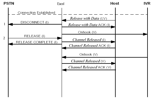
ISDN-initiated Release after Connection to an IVR (Interactive Voice Response)
This call flow shows an existing ISDN to E&M Wink Start interface to an IVR and the ISDN initiating normal call clearing procedures.
1. If the host had the option of "Channel Release Request on ISDN Disconnect" bit set in the ISDN Interface Configure message, the Channel Release Request message would get sent to the host. Otherwise, the host would not be notified of the call being cleared until receiving the Channel Released message. Also, as shown above, if the host did not have "Distant End Release Mode" or "Local End Release Mode" set to park, the CSP would automatically initiate clearing procedures on the channel included in the connection (IVR).
2. The host could insert specific Information Elements in the RELEASE message by using the Release with Data message.
3. The on-hook from the distant end (IVR) could occur at any time and would get reported to the host using the Channel Released message.
4. When detecting the RELEASE COMPLETE, if the host does not need to know the Information Elements then only the Channel Released message is reported. Otherwise, use the Call Processing Event message.
Host-initiated Release after ISDN Connection to an IVR (Interactive Voice Response)
The following call flow shows an existing ISDN to E&M Wink Start interface to an IVR, and the host initiating normal call clearing procedures on the ISDN call.
1. If the host needs to insert its own Information Elements in the DISCONNECT, then send the Release with Data message. Specify both parties in the connection or the other channel (IVR) gets parked.
2. Once the CSP receives the RELEASE message, the RELEASE COMPLETE is returned and a Channel Released message is reported to the host.
IVR-initiated Release after ISDN Connection
The following call flow shows an existing ISDN to E&M Wink Start interface to an IVR, with the IVR initiating normal call clearing procedures for the connection.
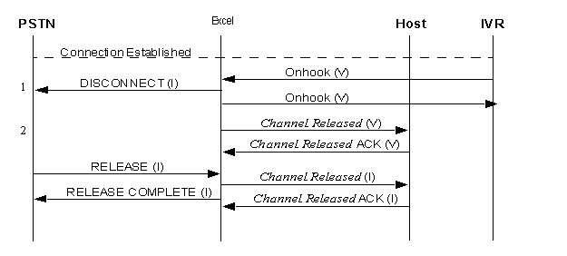
1. If distant end release mode and local end release mode are not configured to park, then the connection automatically gets cleared and a "normal clearing" cause is sent to the ISDN.
2. Both channels send a Channel Released message to the host.
Overlap Receiving
Overlap receiving allows you to provide more information for a call if the SETUP does not contain enough information to route the call.
To use overlap receiving for incoming calls, select the Euro-ISDN PRI variant (0x07) or Euro-ISDN Netside PRI variant (0x17) using the ISDN Interface Configure message. Also, Overlap Receiving must be enabled by using the PPL Configure message to set PPL configuration byte 9 of the L3P Call Control component (0x05) to a value of 0x01. Once the CSP is configured for overlap receiving, the call setup process is transparent and appears to the host as a normal call setup.
When overlap receiving is enabled, the CSP validates the IE data in the incoming SETUP message as a usual call setup. The CSP also checks for the following:
• A sufficient number of digits in the Called Party IE. This number is determined by configuration byte 10 of the L3P Call Control component (0x05), which defaults to a value of 0x10.
• A Sending Complete IE in the SETUP message
If both conditions are false, the CSP sends a SETUP ACK message to the network and goes into overlap receiving mode to obtain more information. If one of the conditions is true, the CSP sends a CALL PROCEEDING and continues with normal call setup.
In overlap receiving mode, the CSP waits for one or more INFORMATION messages from the network. These INFORMATION messages contain the Called Party digit data. Overlap receiving continues until one of the following conditions occur:
• The total number of Called Party digits that the SETUP receives and all the subsequent INFORMATION messages are a sufficient number
• An INFORMATION message receives a Sending Complete IE
• A timeout condition occurs
In the first two conditions, the CSP sends a CALL PROCEEDING message to the network and a Request For Service With Data message is sent to the host with all of the Called Party digits. When a timeout condition occurs, a 15 second L3 Q.931 timer (T302) is set after the CSP sends a SETUP ACK. This timer is reset when each INFORMATION message is received. If this timer expires before the CSP receives an INFORMATION message, the incoming call is cleared with a DISCONNECT message.
As an option, you can override the L3 timer to allow all calls to complete. To do this, configure timer number 2 (using the PPL Timer Configure message) in the L3P Call Control component (0x05) to a value of less than 15 seconds.
If the L3P timer expires before the network receives an INFORMATION message, the CSP sends a CALL PROCEEDING message to the network and a Request For Service With Data message, with all of the Called Party digit data collected up to that point, to the host. You can also use the L3P timer when the sufficient number of digits is indeterminate.
The following call flow shows an incoming call from the network using overlap receiving.
1. If overlap receiving is enabled, the CSP responds to the SETUP with a SETUP ACK.
2. INFORMATION messages received contain additional Called Party digits.
3. The final INFORMATION message may contain a Sending Complete Indication (sending complete IE or # in Called Party IE) or, at this point, the total number of called party digits meets the sufficient number of digits (specified in the value of configuration byte #9 for component #5).
4. The Request for Service message is sent when enough digits are collected and then CALL PROCEEDING is sent.
Overlap Sending
When you select the Euro-ISDN PRI variant (0x07) using the ISDN Interface Configure message, you can use overlap sending for outgoing calls. To select this option, include a Call Type ICB (0x1A) in the Outseize Control message. This ICB tells the CSP to use overlap sending and also determines which mode of overlap sending to use. The CSP uses two methods of overlap sending corresponding to Call Types 1 and 2.
Each Call Type is specified in the first data byte of the Call Type ICB:
• Call Type 1 (L3P-Controlled) -- Include all Called Party digit data that is not in the SETUP in the Call Type ICB as ASCII/IA5 digits following the Call Type byte. When the host sends an Outseize Control message, the CSP indicates a SETUP with whatever Called Party data was included in the Address Data ICB (ASCII/IA5 or ISDN Formatted IEs).
Once the CSP receives a SETUP ACK message from the network, it sends a barrage of INFORMATION messages, one for each of the Called Party digits included in the Call Type ICB. The last INFORMATION message contains a Sending Complete IE. Use this mode mainly for testing purposes.
• Call Type 2 (Host-Controlled) – The Call Type ICB should contain only the Call Type byte 2 as ICB data. In this mode, the CSP sends a SETUP message and waits for a PPL Event Request message from the host to initiate an outgoing INFORMATION message. Send a PPL Event Request message with an event of INFORMATION (0x0D) to the L3P Call Control component (0x05).
The ICB data should be a subtype of ISDN Formatted IEs (0x10) and must contain a Called Party IE with one or more digits. The host can also include a Sending Complete IE as an ISDN Raw IE ICB if this is the last INFORMATION message to be sent.
As with overlap receiving, there is a Layer 3 Q.931 timer running (T304). It is a 30 second timer and is set when a SETUP ACK is received. It is reset when the host initiates an INFORMATION message using a PPL Event Request message. It is disabled when the CSP receives a message from the network that terminates overlap receiving, for example, a CALL PROCEEDING, ALERTING, or CONNECT. When the timer expires, the CSP clears the call by sending a DISCONNECT to the network.
To override this timer, set the L3P Call Control component (0x05) timer number 3 to a value of less than 30 seconds. When the L3P timer expires, the CSP sends an INFORMATION message to the network with a Sending Complete IE to terminate overlap sending and to continue call setup.
The following call flow shows an outgoing call to the network using overlap sending:
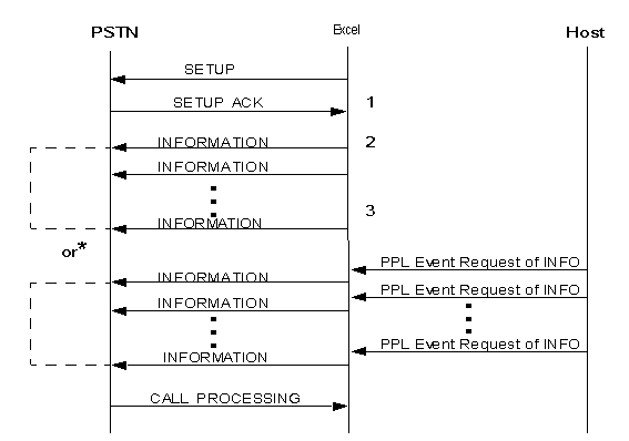
* The overlap sending is either host-controlled or L3P-controlled depending on which Call Type ICB is specified in the Outseize Control message.
1. Once SETUP ACK is received, the CSP sends INFORMATION messages that contain the remaining Called Party digits.
2. INFORMATION messages are sent from L3P.
3. INFORMATION messages are sent from the host using the PPL Event Request.