You are here: CSP Developer’s Guide: Common Channel Signaling > 8 ISDN > ISDN Congestion Control

Overview
The ISDN PRI Congestion Control feature prevents the ISDN card from failing due to call traffic overload. The Congestion Control scheme will help reduce message processing undertaken by the ISDN card and other tasks within the system should incoming traffic on the D channels become excessive.
The ISDN PRI Congestion Control is enabled by default and Dialogic recommends that you do not disable it. The ISDN card measures the number of incoming messages on all supported D channels over set time periods. These congestion control parameters are configurable. If the threshold parameters are set too low, the ISDN card could reject calls that it would be capable of processing. If they are set too high, the CSP will be ineffective in preventing an excessive load situation.
Implementation
The level of congestion is monitored by three components in the ISDN protocol stack:
L3P Call Control component (0x05)
L3 Call Reference component (0x08)
L3 D Channel component (0x0A)
The congestion control parameters for the above components are configurable with the ISDN Interface Configure message (0x60). Congestion parameters configuration information may be retrieved using the ISDN Query message.
When the congestion thresholds are met, an Alarm message is sent to the host. Where Dialogic’s default parameter values are used, congestion is cleared when the average message count is less than 300 messages for 5 seconds.
The Congestion Threshold data fields are common to both ISDN and DASS congestion control schemes. The data fields are formatted to ensure backwards compatibility with the existing DASS congestion control scheme. DASS congestion control used just a single congestion level, this has been changed to Level 2 burst and average thresholds. The default values have also been changed to work with the ISDN scheme, if using DASS then Level 2 burst threshold should be set to 200 and Level 2 average threshold should be set to 1000.
Congestion Level
When the number of incoming messages reaches a certain pre-defined threshold, the D channels are identified as being in a congested state. A congested state results in any new incoming or outgoing call attempts being either rejected or ignored. The D channels will remain in the congested state until the incoming message rate falls below a pre-defined abatement threshold.
The two pre-defined levels of congestion exist with thresholds defined for each. Congestion Level 1 defines the threshold at which calls are rejected. Congestion Level 2, for the higher level, defines the threshold at which point calls are completely ignored.
The congested state is removed once the incoming message rate slows down to a pre-defined, lower threshold known as the abatement level, and stays below this level for a period of time. At this time, processing of the incoming and outgoing calls resumes.
Default Values
The table below shows the default settings for Congestion Control. These settings are applicable on a per ISDN card basis.
|
Description |
ISDN PRI card Defaults |
ISDN Series 3 card Defaults |
|---|---|---|
|
Level 2 burst threshold |
400 messages |
700 messages |
|
Level 2 average threshold |
1900 messages |
3500 messages |
|
Abatement threshold |
500 messages |
900 messages |
|
Burst time window |
1 second |
1 second |
|
Number of samples in average |
10 bursts |
10 bursts |
|
Abatement window |
5 seconds |
5 seconds |
|
Level 1 burst threshold |
350 messages |
600 messages |
|
Level 1 average threshold |
1800 messages |
3300 messages |
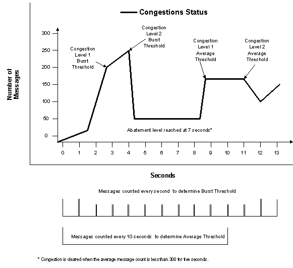
The ISDN congestion control scheme continuously counts the number of incoming messages on an ISDN card. Samples are taken in fixed units of time and are used to determine the congestion level of the card’s associated D channels.
Individual samples are used to determine the ‘burst’ rate. A burst is a count of all incoming messages in a single sample. This enables short excessive peaks in traffic to be accounted for.
A combination of samples is used to determine a moving average. This moving average is a count of all incoming messages over a number of samples. This enables consistent excessive traffic to be accounted for.
Diagram
The figure below shows congestion occurring at various levels using the default settings.
Figure 8-7 Example of Congestion
Configuration
Congestion control on the ISDN card is configurable through the ISDN Interface Configure message. The Single Channel format AIB, (0x0D) is used in this message to specify any one of the individual D Channels but it will apply to all. The AIB should be used to address any individual D channels that have been previously configured using D Channel Assign (0xC4). A new entity, Congestion Threshold (0x0C) has been added to this message to provide congestion threshold values. These values can be changed.
No Congestion during Call Processing
Calls are processed normally.
Congestion Level 1 during call processing
When Congestion Level 1 is reached, a Congestion Level 1 alarm is sent to the host in an Alarm message.
Incoming Calls
Incoming calls are rejected by the Layer 3 Call Reference component (0x08) and a RELEASE COMPLETE message is sent to the network with a Clearing Cause of 0x42 "switching equipment congestion" (0x42).
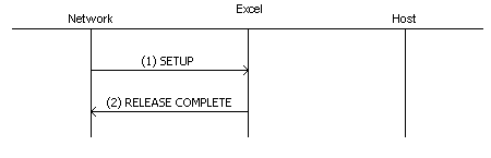
1. A SETUP message is sent from the network to the CSP after Congestion Level 1 is reached.
2. RELEASE COMPLETE with cause code of 0x42 "switching equipment congestion" is sent to the Network.
Important! Calls initiated using the REGISTER message are rejected in the same way.
Outgoing Calls
Outgoing calls are rejected by L3P Call Control component (0x05). On receipt of the Outseize Control message, a NACK is sent to the host with a status of "ISDN congestion" (0x53).
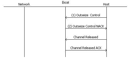
1. When Congestion Level 1 is reached, the host sends an Outseize Control message to the CSP.
2. Outseize Control NACK has a status of 0x53 which indicates Congestion Level 1 has been reached.
Congestion Level 2 during call processing
Incoming Calls
Incoming calls are discarded within the Layer 3 D channel component (0x0A). All messages initiating new calls will not be processed.
Outgoing Calls
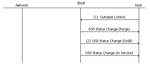
1. When Congestion Level 2 is reached, an Outseize Control message is rejected. The host then is sent a DS0 Status Change of Purge.
2. The DS0 Status Change message is sent to the host with a Purge Reason of 0x0B, FEM Outseize Acknowledgment Timeout.