You are here: CSP Developer’s Guide: Common Channel Signaling > 8 ISDN > Subrate Switching

Overview
The Subrate Switch Controller (SRC) card allows one-way and two-way non-blocking connections and disconnections between any two subrate channels in the CSP.
Configuration
The SRC card requires no configuration. Once the card is inserted into the chassis, it is ready for call processing.
Redundancy
SRC redundancy is achieved using two SRC cards—one active and one standby. When a second SRC card is inserted into the chassis, it is automatically configured as a standby card. No configuration by the host is required. If the active card fails, the standby card automatically establishes control of all subrate connections, with no interaction from the host. The switch supports two SRC cards.
Connection Management
Subrate connections and disconnections are managed using the Subrate Connection Management message. Subrate channels are defined as any number of sequentially ordered bits in an 8-bit DS0.
Multiple subrate channels can be established within a single DS0, as shown in the table below. The host manages connections to ensure that subrate channels within a single DS0 do not overlap (That the same bit is not being used in two different subrate channels).
Table 8-1 Subrate Channels per DS0
|
Channel Size (bits) |
Number of Channels |
|
1 |
8 |
|
2 |
4 |
|
3 |
2 |
|
4 |
2 |
|
5 |
1 |
Connection Scenarios
Both subrate channels in a subrate connection must be the same size. The number of connections supported per subrate channel size is shown in the table below.
The SRC card can simultaneously manage connections of differing rates. For example, a two-bit-to-two-bit connection could be made between any two subrate channels, while a one-bit-to-one-bit connection is made on two other subrate channels.
The number of simultaneous connections supported depends upon the combination of subrate channel sizes used. For example, a single switch can simultaneously connect 1,024 8-bit channels (512 two-way connections) and 4,096 two-bit channels (2,048 two-way connections).
Connection Types
The SRC card supports both two-way and one-way subrate connections. The connection type is determined by the Action field in the Subrate Connection Management message. Multiple one-way connections with the same source subrate channel can be used to establish a broadcast, as shown in the Examples section of the message, Subrate Connection Management 0x0D 3-74, in this document.
Disconnection
The host is responsible for tearing down subrate connections. The switch cannot tear down a subrate connection for any reason, including the loss of a span, except in response to a Subrate Connection Management message from the host.
Table 8-2 Connections supported per subrate channel size
|
Subrate Channel Size (bits) |
Rate |
Number of Connections |
|---|---|---|
|
8 |
64 Kbps |
1,024 |
|
7 |
56 Kbps |
1,024 |
|
6 |
48 Kbps |
1,024 |
|
5 |
40 Kbps |
1,024 |
|
4 |
32 Kbps |
2,048 |
|
3 |
24 Kbps |
2,048 |
|
2 |
16 Kbps |
4,096 |
|
1 |
8 Kbps |
8,192 |
Subrate Connection Management Message
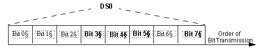
The Subrate Connection Management message is used to establish subrate connections and to tear them down. The LSB of Subrate Channel field in this message indicates the first low-order bit of the subrate channel in the DS0. Bits are transmitted Most Significant Bit (Bit 7) to Least Significant Bit (Bit 0) as shown in the figure below.
The Number Of Bits In Subrate Channel field in this message indicates the number of bits (0-7) in the subrate channel. To ensure that the subrate channel does not overlap another DS0, the number of bits in the subrate channel plus the Bit Offset must not exceed eight.
The Action field in this message indicates a one-way connection (0x01), a two-way connection (0x02), or a disconnection (0x03).
Figure 8-10 Order of Bit Transmission
Examples
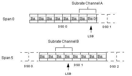
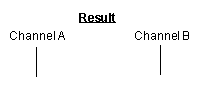
This section includes examples of one-way and two-way connections and disconnections using the subrate channels shown in the figure below.
Figure 8-11 Subrate Channel A and B
Two-Way Connection
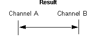
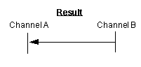
The figure below shows the establishment of a two-way connection between the two subrate channels.
Figure 8-12 Two-Way Connection - Result
One-Way Connection
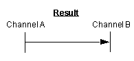
The figure below shows how a one-way connection is established between the two subrate channels. In this example, subrate Channel A is the transmission source for subrate Channel B.
Figure 8-13 One-way subrate connection - Result
Two-Way Disconnection
The figure below shows the use of the API format of the Subrate Connection Management message to tear down an established connection. The message is identical to that used to establish the connection except that the Action field (Byte 24) is set to Disconnect (0x03) as shown in the next table.
Figure 8-14 Two-Way Disconnection - Result
One-Way Disconnection
For a one-way disconnection, the same subrate channel is entered as both Subrate Channel A and Subrate Channel B in the message.
If a one-way connection is established, it causes termination of the connection at both ends.
Figure 8-15 One-Way Disconnection - Result
If a two-way connection is established, it results in a one-way connection with the subrate channel indicated in the message as the source channel.
The figure below shows teardown of a two-way connection through the use of the Subrate Connection Management API message. This action results in a one-way connection with Subrate Channel B as the source.
Figure 8-16 Two-Way Connection - Result