You are here: CSP Developer’s Guide: Common Channel Signaling > 5 TUP, BT IUP & SSUTR2 > TUP Virtual CIC

Overview
The TUP Virtual CIC is a protocol configuration that enables application systems to use and manage the functions of China SS7 TUP through Cantata software. The TUP Virtual CIC feature meets all standard Cantata software requirements, including fault tolerance and SS7 hot-swappable redundancy. This means the TUP Virtual CIC does not affect connectivity or performance.
Please note the following:
• A maximum of 2,048 Virtual CICs can be configured in one SS7 card.
• Product Licensing is supported for TUP Virtual CICs.
The TUP Virtual CIC protocol controls Circuit Identification Codes (CICs), which function as virtual entities that are not physically attached to the CSP. Management of the physical voice circuits is given instead to the host, and the CSP manages only the signaling links, which are the single physical connection to the SS7 network. The Matrix Controller Series 3 is used only for SS7 card configuration, and for passing messages between the host and the SS7 card.
This message handling bypasses all CSP Call Control processing and functionality. Messaging for call processing is done by PPL Event Indication and PPL Event Request messages only.
Please refer to the following recommendation for software requirements:
• ITU-T Q.721 - Q.724 (Blue Book TUP)
• API Reference
Excel’s SS7 protocol software supports Telephone User Part (TUP) call control, which is the basis for the TUP Virtual CIC. Most TUP Virtual CIC messages map directly to host API messages.
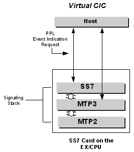
Cantata uses the PPL environment to utilize the TUP Virtual CIC; this environment consists of the following modules, also shown in the figure below for virtual CIC software architecture:
• CSP Signaling, including Layer 3 Plus (L3P) and Layer 3 Plus TUP (L3P TUP), which is modified to support Virtual CICs.
• TUP
• Message Transfer Part (MTP), including MTP2, and MTP3
Each module contains one or more PPL components, which are automatically used when a module is selected. The PPL components are described in SS7 PPL Information.
The figures below illustrate the functional modules involved in the TUP Virtual CIC implementation of Virtual CICs on the SS7 card, and show how the signaling stack integrates into CSP architecture.
Figure 5-1 Virtual CIC Software Architecture
.
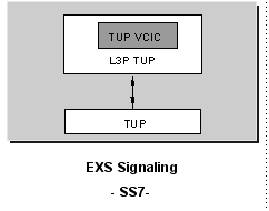
Figure 5-2 L3P TUP with TUP Virtual CIC
MTP Message Tracing in TUP Virtual CIC
The principal objective of the SS7 MTP Message Tracing feature is to send the Raw Data between MTP3 and MTP2 to the host. This will occur in response to the PPL Configure message with a "Diagnostic Enabled" option, which allows all MTP Raw Data (both transmitted and received) to be presented to the host. If that option is disabled, then MTP3 will stop sending Raw Data to the host.