You are here: CSP Developer’s Guide: Common Channel Signaling > 5 TUP, BT IUP & SSUTR2 > TUP Virtual CIC Call Control Management and Maintenance
TUP Virtual CIC Call Control Management and Maintenance

Overview
The host manages the TUP Virtual CIC call control and circuit management. The Virtual CIC sends all call processing messages directly to Host. Virtual CICs are different from L3P TUP CIC:
• The host is notified of service state changes and channel purges by the PPL Event Indication message, rather than by the DSO Status Change message.
• PPL event indications and requests are sent for an IAM instead of generating an outseize or receiving an RFS. In the event of call failure, there is no Outseize Control NACK and a PPL Event Indication with the reason for the call failure is sent to the host.
• The Outseize Control message is not used for L3P Virtual CICs.
• PPL event indications and requests are sent for Alerting (ACM), Answer (ANx) and Release (CLF).
• The host is notified when L3P CIC receives an incoming Continuity Test (COT) message request and the host then performs the loopback, without any CSP Call Control interaction.
• The host reports the span status to the CSP using the PPL Event Request message. L3P CIC takes appropriate action.
• If L3P CIC performs a purge, CSP Call Control is not informed. Instead, a PPL Event Indication for a CIC status change is sent to the host. This PPL Event Indication is equivalent to a DSO Status Change message for a physical CIC. It contains an ICB of subtype 0x22 with data length of two:
Data [0] -- Status (1=OOS, 2=INS)
Data [1] -- Status change reason (such as purge code)
When we initiate a purge the channel goes to Out of Service and comes In Service immediately. Thus, when we purge OOS, we send the purge Reason in Data [1]. If Out of Service occurs for any other reason, Data [1] will be "0", as shown in the following table:
|
Data [1] OOS (0x0199) |
Data [1] INS (0x0196) |
|---|---|
|
00 = Host/Normal |
00 |
|
01 - FF = Purge Reasons |
|
This section includes call flow examples for the TUP Virtual CIC outgoing call scenarios for ITU.
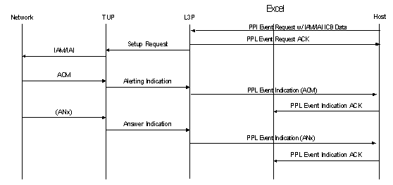
1. The host sends to L3P a PPL Event Request message, which contains an SS7 Parameters ICB with IAM or IAI ICB data.
2. L3P sends an acknowledgment back to the host and generates a Setup Request to TUP.
3. TUP will generate an IAM or IAI request to the network, depending on the ICB data. Any protocol timers there are will be started.
4. When the network receives the IAM or IAI message, it sends an ACM to TUP, which in turn sends an Alert Indication to L3P. Then L3P sends a PPL Event Indication ACM to the host. This means that when the host receives the ACM, it has the complete address and does not need additional digits. The host acknowledges the PPL Event Indication to the CSP.
5. The network sends an ANx (indicating the type of call) to TUP, which sends an Answer Indication to L3P.
6. L3P generates a PPL Event Indication containing the ANx to the host. The host sends the acknowledgment to the CSP.
Outgoing Call with Remote Clear Back
1. The network generates a CBK, clear back message, and sends it to the CSP. TUP sends the message to the host via L3P as a PPL Event Indication with CBK.
2. L3P acknowledges the CLF Indication with an RLG request back to the network. The host acknowledges the PPL Event Indication. The call is cleared.
3. The host acknowledges receipt of the message and generates a PPL Event Request, which contains an SS7 Parameter ICB with parameters for the outgoing CLF message request (for the channel to be released with data). The message is sent to the network.
4. The network responds by generating an RLG acknowledgment. This is sent to the host using the CSP as a PPL Event Indication with the Data ICB for RLG. The host acknowledges the PPL Event Indication. The outgoing call is released.
Call Failure Received from the Network
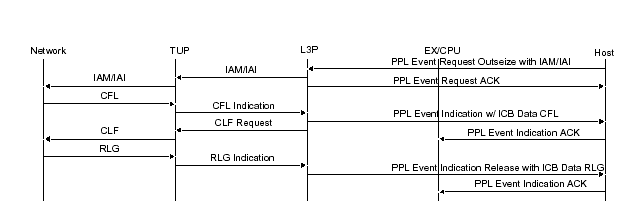
1. The host sends an Outseize Control message in a PPL Event Request to the CSP, which acknowledges the request. The CSP generates an IAM or IAI out to the network for the call.
2. The network sends the host notification of the CFL through the CSP, which generates a PPL Event Indication containing an SS7 Parameter ICB, with parameters for the CFL message. This message is sent to the host and acknowledged.
3. The CSP sends the CLF request to the network.
4. The network responds by generating an RLG acknowledgment. This is sent to the host via the CSP as a PPL Event Indication with the Data ICB for RLG. The host acknowledges the PPL Event Indication. The call is released.
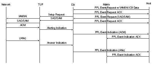
1. The host sends to L3P a PPL Event Request message, which contains an SS7 Parameters ICB with IAM or IAI ICB data. L3P sends an acknowledgment back to the host and generates a Setup Request to TUP.
2. TUP will generate an IAM or IAI request to the network, depending on the ICB data. Any protocol timers there are will be started.
3. The host then sends to L3P a PPL Event Request message which contains an SS7 Parameters ICB with an SAO or SAM message, indicating the need for additional information (digits).
4. The network receives the IAM or IAI message. It sends an ACM to TUP, which in turn sends an Alert Indication to L3P. Then L3P sends a PPL Event Indication ACM to the host. This means that when the host receives the ACM, it has the complete address and does not need additional digits. The host acknowledges the PPL Event Indication to the CSP.
5. The network sends an ANx (indicating the type of call) to TUP, which sends an Answer Indication to L3P.
6. L3P generates a PPL Event Indication containing the ANx to the host. The host sends the acknowledgment to the CSP.
This section includes call flow examples for the TUP Virtual CIC incoming call scenarios for ITU.
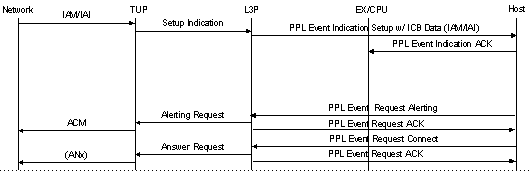
1. L3P alerts the host by sending a PPL Event Indication Setup with IAM or IAI ICB Data through the CSP. The host acknowledges the PPL Event Indication to the CSP.
2. The host then generates a PPL Event Request message to send an Alert Indication to TUP, which sends an ACM to the network. L3P acknowledges the PPL Event Request.
3. The host then sends a PPL Event Request Connect to L3P, indicating that the call has been answered.
4. L3P acknowledges the PPL Event Request and sends an Answer Request message to TUP. Then TUP sends an ANx to the network, successfully completing the procedure.
Basic Call Setup with Overlap Operation
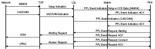
1. The network generates an IAM or IAI message to TUP, which then sends a Setup Indication to L3P.
2. L3P alerts the host by sending a PPL Event Indication Setup with IAM or IAI ICB Data through the CSP. The host acknowledges the PPL Event Indication to the CSP.
3. If there are not enough digits in the IAM/IAI, the network will send an SAO or SAM to TUP to provide additional information. TUP will generate a PPL Event Indication for SAO/SAM and send it to the host. The host acknowledges the PPL Event Indication to the CSP.
4. The host then generates a PPL Event Request message to send an Alert Indication to TUP, which sends an ACM to the network. L3P acknowledges the PPL Event Request.
5. The host then sends a PPL Event Request Connect to L3P, indicating that the call has been answered.
6. L3P acknowledges the CLF Indication with an RLG request back to the network. The host acknowledges the PPL Event Indication. The call is cleared.
Clear Forward Received from the Network
1. The network generates a CLF message clear the call.
2. The message is sent to the CSP, and then to the host using a PPL Event Indication message for SS7 ICB Data with CLF.
3. The host acknowledges the CLF message as received.
The example call flows included in this section show maintenance and release procedures for incoming and outgoing calls.
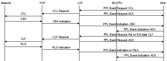
1. The host generates a PPL Event Request with the CCL message to clear the call and sends the request to the network via the CSP.
2. The network responds with a Clear Back indication, which is sent in a PPL Event Indication from the CSP to the host. The host acknowledges the PPL Event Indication.
3. The host then sends a PPL Event Request which contains an SS7 Parameter ICB with parameters for the outgoing CLF message request (for the channel to be released with data). The message is sent to the network.
4. The network responds by generating an RLG acknowledgment. This is sent to the host via the CSP as a PPL Event Indication with the Data ICB for RLG. The host acknowledges the PPL Event Indication. The outgoing call is released.
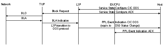
1. The host sends a Service State Configure to put the CIC Out of Service.
2. The CSP sends a BLO (default OOS operation) to the network.
3. The network sends a BLA to the CSP, which sends a PPL Event Indication for CIC OOS to the host. The CIC is put OOS and marked unequipped after receiving BLA from the network. This PPL Event Indication message is the same as sending a DSO Status Change.
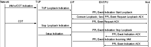
1. When an IAM is received with a continuity test indication, L3PTUP will send a PPL Event Indication to the host. The host is controlling the physical circuits; thus, the host will connect the loopback and send a loopback acknowledgment to the CSP 2000, so that it can synchronize the CIC state with the physical CIC state.
2. After the continuity test is successful, COT will be received from the network and the CSP 2000 will send a PPL Event Indication to the host to stop the loopback. The host should remove the loopback.
3. L3PTUP will receive a setup indication from TUP. L3PTUP will send an Incoming Call PPL Event Indication to the host.
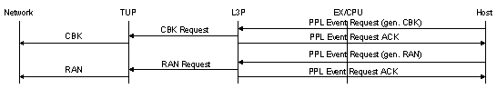
1. The host generates a PPL Event Request with the CBK message and sends the request to the network via the CSP. L3P sends acknowledgment to the host.
2. The host then sends a PPL Event Request which contains an SS7 Parameter ICB with parameters for the outgoing RAN message request (a re-answer signal for recorded announcements). The message is sent to the network.
Outgoing Call Release, Send Clear Forward
1. The host acknowledges the PPL Event Indication and the outgoing call is released.
PPL event request IAM on stack0, cic 0100
H->X [ 00 21 00 44 00 00 ff 00 01 31 07 00 00 00 09 87 01 00 00 11 00 3c 01 02 1c 09 01 01 01 03 04 87 26 23 91 ]
X->H [ 00 07 00 44 00 00 ff 00 10 ]
PPL event indication incoming call on stack1, cic 0100
X->H [ 00 28 00 43 00 7f ff 00 01 31 07 01 00 00 01 23 01 00 00 11 01 91 01 02 1c 10 01 01 03 01 01 0a 02 02 00 00 03 04 87 26 23 91 ]
PPL event request ACM on stack1, cic 0100
H->X [ 00 1e 00 44 00 00 ff 00 01 31 07 01 00 00 01 23 01 00 00 11 00 01 01 02 1c 06 04 01 01 0c 01 05 ]
X->H [ 00 07 00 44 00 00 ff 00 10 ]
PPL event indication ACM on stack0, cic 0100
X->H [ 00 1e 00 43 00 80 ff 00 01 31 07 00 00 00 09 87 01 00 00 11 00 2e 01 02 1C 06 04 01 01 0c 01 05 ]
PPL event request answer on stack1, cic 0100
H->X [ 00 1b 00 44 00 00 ff 00 01 31 07 01 00 00 01 23 01 00 00 11 00 05 01 02 1c 03 06 01 00 ]
X->H [ 00 07 00 44 00 00 ff 00 10 ]
PPL event indication answer on stack0, cic 0100
X->H [ 00 1b 00 43 00 86 ff 00 01 31 07 00 00 00 09 87 01 00 00 11 00 2f 01 02 1C 03 06 01 00 ]
PPL event request release on stack0, cic 0100
H->X [ 00 15 00 44 00 00 ff 00 01 31 07 00 00 00 09 87 01 00 00 11 00 3d 00 ]
X->H [ 00 07 00 44 00 00 ff 00 10 ]
PPL event indication clear forward on stack1, cic 0100
X->H [ 00 1b 00 43 00 87 ff 00 01 31 07 01 00 00 01 23 01 00 00 11 01 97 01 02 1C 03 06 04 00 ]
PPL event indication release guard on stack0, cic 0100
X->H [ 00 15 00 43 00 83 ff 00 01 31 07 00 00 00 09 87 01 00 00 11 01 9b 00]