You are here: CSP Developer’s Guide: Internet Protocol > 6 Call Agent > Call Flows

Overview
The call flows in this section cover the following scenarios:
• Traditional Switching SIP-to-SIP Call
• Call Agent Switching with Host Application Control
• Dual Switching Scenario
Includes diagram of example
• Dual Switching DSP-ONE Based Prompt and Collect Scenarios
Includes diagram of example
• Mid-Call RFC 2833 DTMF Signaling by Near-End
Includes diagrams of three examples
Traditional Switching SIP-to-SIP Call
Traditional switching is supported in this release and in previous releases.
The following call flow shows how a traditional bearer-switched SIP-to-SIP call is established through the CSP. The CSP acts as a back-to-back user agent in that the SIP end-points signal with the CSP only, and connect to VDAC RTP ports. The VDAC RTP ports are internally connected over the Time Slot Interchange (TSI) fabric for an end-to-end speech path. This internal connection is the "hairpin."
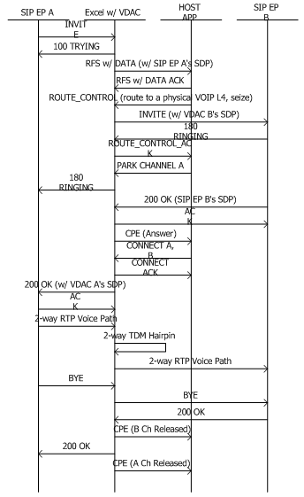
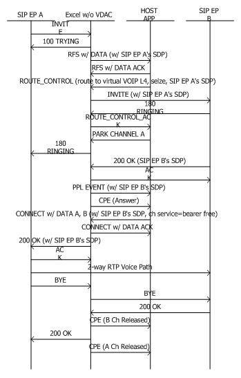
Call Agent Switching with Host Application Control
The following call flow shows Call Agent switching with host application control. This call flow is a typical example of how a host application controls and participates in network signaling data transfer from one side to the other. From the OAM&P perspective, all Call Agent calls require host applications to configure virtual span/channels in the system. Virtual span/channels are essentially span/channels assigned to virtual slots that contain virtual VoIP cards. Additionally, you must configure the router so that virtual span/channel-based resource groups are defined and associated with appropriate route lookup rules.
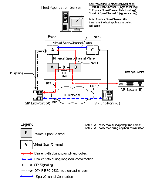
The following call flow and Dual Switching Scenario for Pre-Paid Application with External IVR depicts a normal dual switching scenario. The caller is first connected to an Interactive Voice Response (IVR) system through the bearer-switched path provided by the CSP. When the host application releases the IVR call leg, the caller is connected to the long-haul called party, bypassing the bearer switching facilities of the CSP. Overall, the caller’s connection to the IVR system is an intermediary step that can be repeated any number of times; however, the caller’s connection to the IVR typically alternates with the connection to the long-haul party.
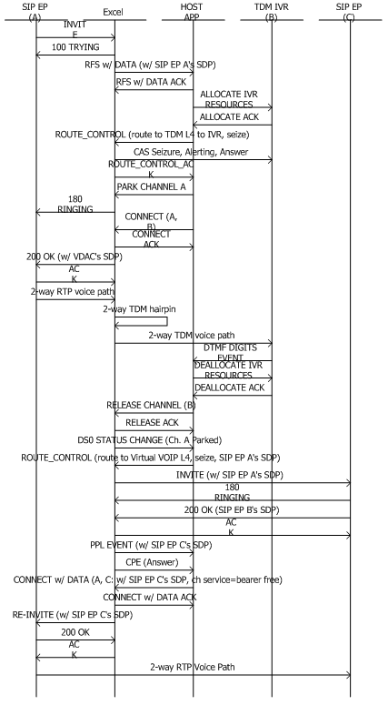
Figure 6-5 Dual Switching Scenario for Pre-Paid Application with External IVR
Dual Scenario DSP-ONE Based Prompt and Collect Scenarios
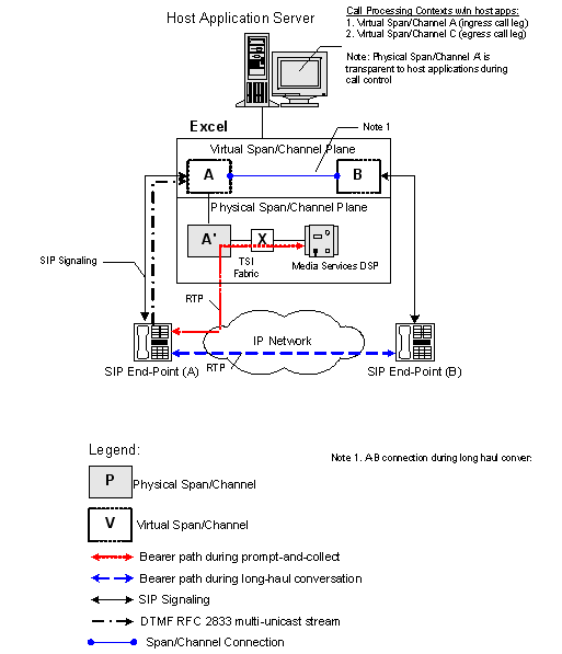
It is transparent to Call Agent software whether media services are run on an external IVR or an internal DSP-ONE card. The call flow below shows a dual switching scenario where a DSP-ONE card is used for media services. Note that only A and B channels are shown because the DSP-ONE services are requested on channel A itself. This scenario is illustrated in Dual Switching Scenario for Pre-Paid Application with DSP-ONE Card following this call flow.
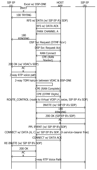
Figure 6-6 Dual Switching Scenario for Pre-Paid Application with DSP-ONE Card
Mid-Call RFC 2833 DTMF Signaling by Near-End
The call flow below shows the Mid-call RFC 2833 DTMF signaling by near-end scenario. In this scenario, the caller specifically instructs the CSP for long-distance call termination and reconnection with an IVR. The CSP uses a special sequence of DTMF digits
(such as long # sequence) to communicate and decipher the caller’s intent. Following this call flow are three diagrams showing three different environments using RFC 2833 multi-unicast.
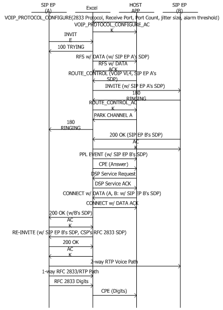
Figure 6-7 Call Agent RFC 2833 multi-unicast in SIP Softswitch Environment
In the following diagram, the CSP uses an SDP message to re-invite the Media Gateway (via the softswitch) to offer two media streams:
• audio to/from the remote end-point
• telephone event - RFC 2833 multi-unicast
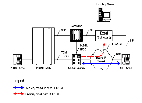
Figure 6-8 Call Agent RFC 2833 multi-unicast in SIP Gateway Environment
In the following diagram, the CSP uses an SDS message to re-invite the SIP Gateway to offer two media streams:
• audio to/from the remote end-point
• telephone event - RFC 2833 multi-unicast
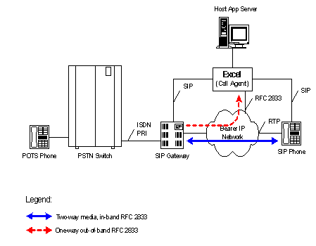
Figure 6-9 Call Agent RFC 2833 multi-unicast in SIP End-Point Environment
In the following diagram, the CSP uses an SDS message to re-invite the ingress SIP end-point to offer two media streams:
• audio to/from the remote end-point
• telephone event - RFC 2833 multi-unicast
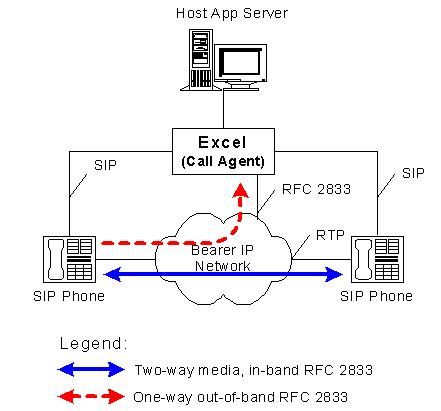
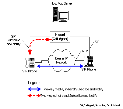
Figure 6-10 Call Agent Subscribe and Notify in SIP End-Point Environment
In the following diagram, the CSP uses an SDS message to re-invite the ingress SIP end-point to offer two media streams:
• audio to/from the remote end-point
• telephone event - Subscribe and Notify. The CSP is the subscriber and the remote end point is the notifer.