You are here: CSP Developer’s Guide: Internet Protocol > 9 H.323 Software > Internal Architecture

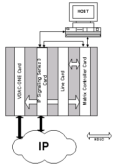
The line cards T-ONE, E-ONE, J-ONE, DS3, and VDAC-ONE (or IP Network Interface Series 2) card communicate with the CSP Matrix Series 3 Card over the internal HDLC bus. In addition, the IP Signaling Series 3 card and the VDAC-ONE (or IP Network Interface Series 2) card connect directly to the IP Network. The Host, IP Signaling Series 3 Card, and CSP Matrix Series 3 Card communicate over the Ethernet LAN.
Figure 9-3 The CSP chassis
IP Call Processing and Translation
The CSP processes H.323 calls as follows:
1. Any H.323-related message from the IP network is received on the IP Signaling Series 3 card and processed. If necessary, the message is translated and sent to the CSP Matrix Series 3 Card.
2. Any host message destined for the IP network is sent first to the CSP Matrix Series 3 Card, where it is processed and translated, then sent to the IP Signaling Series 3 card.
3. The IP Signaling Series 3 card then forwards the message to the IP Network.
4. The CSP Matrix Series 3 Card also handles all communication between the IP Signaling Series 3 card and the VDAC-ONE (or IP Network Interface Series 2) card.
5. The VDAC-ONE (or IP Network Interface Series 2) card is responsible for transmitting and receiving the IP RTP data stream.
The CSP as H.323 Protocol Converter
The CSP acts as an H.323 gateway by connecting the PSTN to an IP network. In the CSP, any inbound PSTN call (for example, T1) is connected to the outbound IP network by connecting the VoIP channels and T1 channels. For example:
1. A caller with a traditional analog telephone dials the number of an IP telephone.
2. The signal comes into the CSP.
3. The CSP Matrix Series 3 Card sends a Request for Service message to the host computer.
4. The host sends a Route Control message through the CSP Matrix Series 3 Card to the IP Signaling Series 3 card.
5. The IP Signaling Series 3 card sets up the call to the IP phone.
6. The host connects the channels.
Figure 9-4 PSTN-to-IP call
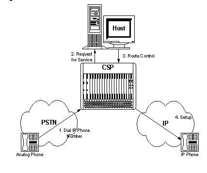
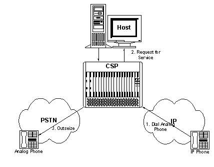
Figure 9-5 IP-to-PSTN call
H.245 Tunneling
The H.245 messages are encapsulated and carried between H.225 controlled endpoints within H.225 messages. This way of "piggy-backing" an H.245 message to an H.225 message is the H.245 Tunneling feature.
H.245 Tunneling is optional and negotiable between communicating H.323 endpoints. If both endpoints support this option, usually the H.245 Media Controlled messages are exchanged with the tunneling mechanism.
The CSP can accept H.245 Tunneling for all inbound calls even if outbound calls do not offer this capability. However, H.245 Tunneling for outbound H.323 calls is available only when it is enabled for inbound H.323 calls.
Configuring H.245 Tunneling for Inbound H.323 Calls
Send the following TLV to the CSP in the VoIP Protocol Configure message (0x00EE).
H.225 Tunneling Configure TLV (0x02D5)
Configuring H.245 Tunneling for Outbound H.323 Calls
Send the following TLV to the CSP with either the Route Control (0x00E8) message or Outseize Control (0x002C) message.
H.245 Outbound Tunneling TLV (0x27E4)
Configuring with CSA
Refer to Configuring H.323 in the SwitchKit Converged Services Administrator User’s Guide.