You are here: CSP Developer’s Guide: Internet Protocol > 9 H.323 Software > Software Overview

The H.323 VoIP Gateway complies with H.323 Version 2.0, and therefore supports all gateway Registration, Admission, and Status (RAS) functions.
The H.323 VoIP Gateway provides an interface between the PSTN and IP network for voice calls. IP-to-IP calls are also supported on the gateway. The H.323 stack is implemented on the specially-configured IP Signaling Series 3 card. The IP Signaling Series 3 card has a special software load that includes IP Signaling interface support and the H.323 stack.
Assuming adequate network conditions, the CSP delivers carrier-class voice quality over H.323.
The CSP H.323 offering on the CSP provides both signaling and media capability, so application developers do not need to add these features separately. The H.323 signaling is provided by the IP Signaling Series 3 card and media is provided by the VDAC-ONE or IP Network Interface Series 2 card.
Seamless PSTN-IP Signaling Interworking: SIP/H.323/SS7/ISDN
This H.323 implementation uses Universal Protocol Data Format (UPDF) to provide seamless protocol interworking, with no need for protocol-specific messages. This interworking includes calls from PSTN-to-PSTN, IP-to-IP, PSTN-to-IP, and IP-to-PSTN.
The User Input Indication (UII) message is available in the CSP to transmit inputs from the user interface to the receiver. The inputs could be a button that the user presses on the PSTN side of the call such as a DTMF keypad or hookswitch information. The UII message transmits the hookflash and DTMF signal information on the IP side of the call.
The hookflash is a common input indicating a brief on-hook condition that occurs during a call. For example, during a call, the phone user quickly depresses and then releases the hook on their telephone. It is not long enough in duration to be interpreted as a signal to disconnect the call; however, telephone switches and PBXs are frequently programmed to intercept hookflash indications and use them to allow a user to invoke supplemental services. For example, your local service provider may allow users to enter a hookflash to switch between calls if the user subscribes to a call waiting service.
To enable the CSP to transmit the PPL Event Indication message to the host, you must set Configuration Byte 1 for PPL Component L3P H.225 (0xA1) to 0x01. To disable, set the configuration byte to 0x00.
See the following PPL Component in this chapter.
PPL Component for H.225 - 0x00A1
The following data ICBs support the User Input Indication message. See the following in the ICB Chapter in the API Reference:
• 0x5B IP Signaling Series 3 Card ID
• 0x5C H.323 Hookflash Received (no data)
• 0x5D H.323 DTMF Signal Input Received
• 0x5E H.323 Signal Update Input Received
• 0x5F H.323 Alphanumeric Input Received
• 0x62 Remote Endpoints UII Capabilities
The CSP supports multiple alias addresses such as E.164, H.323Id, URL, and e-mail for the IP Signaling Series 3 card and remote H.323 endpoints.
The following TLVs support alias addressing:
• 0x02C1 Vendor ID
• 0x02C4 Gateway E164
• 0x02C6 Gateway URL ID
• 0x02C7 Gateway E-mail ID
• 0x27C4 Source IP
• 0x27C5 Source Port
• 0x27D8 Source H.323 ID
• 0x27D9 Source URL
• 0x27DA Source E-mail
• 0x27DC Remote H.323 ID
• 0x27DD Remote URL
• 0x27DE Remote E-mail
Gatekeeper Support
The CSP interfaces to gatekeepers from leading companies. This feature requires the CSP to send a gateway technology prefix in the registration request (RRQ). Use this prefix to configure the gateway's routing table or database in the gatekeeper. Include the TLV below in the VoIP Protocol Configure message to create and send the prefix.
0x02D3 Gateway Technology Prefix
In this CSP H.323 implementation, the following specifications are supported:
• H.225.0 (RAS, Q.931, RTP/RTCP)
• H.245 and audio codecs
The VDAC-ONE or IP Network Interface Series 2 card provides the RTP stream for the H.323 call.
The H.323 software gets the RTP Payload Type and Payload size from the Route Table or Route Control message. If the type and size are not specified in either of those, the H.323 software uses the defaults.
Call Progress and Alerting Messages
The Progress message is an optional Q.931 call setup message. It can be sent by an H.323 gateway to indicate the progress of a call when interworking with a Switched Circuit Network (SCN). This message can also be sent by an H.323 endpoint before the Connect message is sent, depending on the supplementary service interaction.
On an H.323 call, Call Alerting and Progress messages can contain a Progress Indicator Information Element (IE) to describe an event that occurred during the life of the call. The CSP will establish a voice path when required.
The CSP does the following:
• Processes an optional Progress message on an outgoing call.
• Determines if the Q.931 Progress Indicator IE is present in the Alerting or Progress messages on a call.
• Sends a PPL event indication to the host when the CSP receives an Alerting or Progress message. A message is sent to the
VDAC-ONE (or IP Network Interface Series 2) card to establish the voice path.
• Receives a PPL Event Request of Alerting or Progress from the host with the progress indicator.
• Transmits a Progress message to network.
• Transmits the appropriate Release Complete Reason in Release Complete message to the network. The Release Cause Codes are listed in the Release Cause Code TLV (0x27E3) in the Tag Length Value Blocks chapter in the API Reference.
This functionality works in gateway or normal (non-gateway) mode.
Dual Ethernet Port
You can configure the second Ethernet port on the
IP Signaling Series 3 card to separate the H.323 signaling traffic from the host control traffic. Dialogic recommends having the host-to-CSP traffic carried on Ethernet port A and the H.323 signaling traffic carried on the Ethernet port B.
The BOOTP server is required to configure Ethernet port B.
The additional information is carried in the vendor specific area of the BOOTP response. You modify the BOOTP configuration to include new entries to carry the IP Address, Gateway IP Address, and Subnet Mask for the second physical Ethernet port.
Configuring the second Ethernet port is optional but if you enter an IP Address for Ethernet port B you must enter an associated Subnet Mask.
Important! Although a gateway IP Address may be configured for both Port A and Port B, only one is utilized. If two gateway IP addresses are configured, one for Port A and one for Port B the one specified for Port A will be used. Therefore, Dialogic recommends that you configure only one gateway IP Address and that it be on Port B.
If you do not configure the second ethernet port, it is internally set to the same values configured for the first ethernet port.
For the associated procedure, refer to Configuring Dual Ethernet Ports on IP Signaling Card in the Application Development chapter in the Developer Guide: Overview.
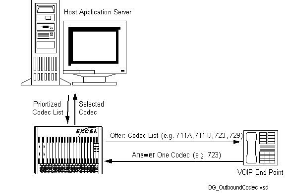
Codec List in H.323-Initiated Offers
The CSP can send a list of up to five supported codecs in an H.323 offer to an endpoint when establishing a media session. The receiving endpoint selects one codec from that list and reports the selection back in the answer message to the CSP.
The following applies to this feature:
• The codec list is applicable for calls that use SIP or H.323 signaling and is not for clear-channel VoIP calls. For SIP signaling refer to Host Control Method of SIP 180 Provisional Response Generation.
• The IP Network Interface card must use Profile 2.
• The VDAC-ONE card must use Profile 0.
Without this feature, the call might not get established because the CSP could include a codec type that endpoint will not accept.
The figure below provides an overview of this process.
Figure 9-1 Codec List in Offer
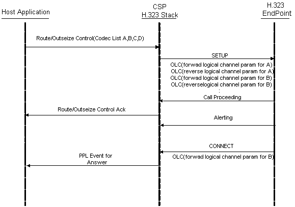
Outseize Control messages
The host application provides the codec list and sends the list in the Outseize Control message as shown in Host Provides Codec List:
Figure 9-2 Host Provides Codec List
TLVs Used
Use the following TLVs in the Outseize Control message to include the codec types:
• 0x29FF - Local End-Point Media Info
• 0x2A0E - Media Connection Address
• 0x2A01 - Per Media Stream Information
• 0x2A03 - Media Type
• 0x2A07 - Media Port
• 0x2A02 - Per Codec Info
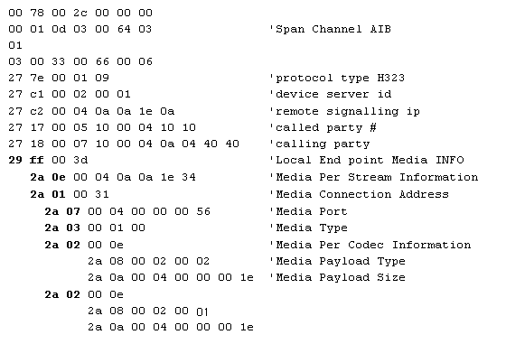
The Outseize Control Message Trace shows how to use these TLVs in the Outseize Control message. Note that the Outseize Control message cannot exceed 260 bytes.
Important! DO NOT use the following TLVs for these codec types:
• 0x0100 - RTP Payload Type
• 0x0101 - RTP Payload Size
• 0x27B0 - RTP Payload Type
• 0x27B1 - RTP Payload Size
Outseize Control Message Trace
The following trace for the Outseize Control message shows the nested TLVs containing the codec information.
H.323 Host Control Direct and Gatekeeper Routed Calls
The H.323 protocol resident in the IP Signaling Series 3 card enables the CSP (gateway) to communicate with other H.323 gateways and gatekeepers in the call server network architecture.
Prior to this feature, the Gateway (CSP) supported either gateway (direct calls) or gatekeeper routed calls at any one time. When the Gateway (CSP) was registered with a gatekeeper it would process all the calls as Gatekeeper routed calls.
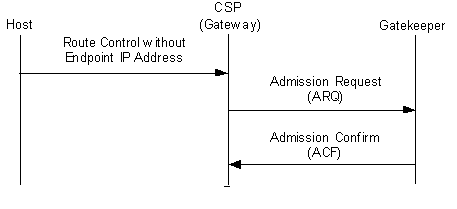
If the CSP is registered with a Gatekeeper, the CSP may send an ARQ (Admission Request) message to the Gatekeeper to request information about a remote endpoint. If the CSP chooses to send an ARQ to the gatekeeper, when the gatekeeper responds with the ACF (Access Confirmed), the response will determine if the CSP sends the call to the gatekeeper or directly to the remote endpoint.
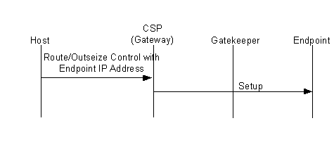
Direct Routed
If the remote endpoint IP address TLV 0x27C2 is included in the Route Control/Outseize message, then the CSP will send the call to the remote endpoint IP address that is specified in the TLV 0x27C2. The CSP will not send the ARQ to the gatekeeper.
Gatekeeper Routed
If the remote endpoint IP Address TLV 0x27C2 is omitted from the Route Control or Outseize Control message, then the CSP sends the ARQ message to the Gatekeeper. When the ACF is returned, the CSP looks in the message to determine where to send the call. The CSP will send the call either to the remote endpoint IP address provided by the gatekeeper or to the gatekeeper as specified in the ACF message.
The end result is the CSP does not actually modify the gatekeepers’ behavior. The CSP acts differently based upon data included in the Route Control/ Outseize Control message.
Invoking
To invoke this feature use the Route Control (0x00E8) message with the Remote End Signaling IP Address (Q.931) (0x 27C2) TLV. This TLV provides the remote endpoint IP address for the call. This TLV will be used for each call to determine whether the ARQ and ACF message exchanged is implemented for that call.
Important! The Remote End Signaling Port (Q.931) (0x27C3) TLV specifies the remote signaling port. The defaults are: port number 1719 for gatekeeper routed calls and port number 1720 for gateway routed calls. This TLV is only necessary when using non-standard values.
H.245 Tunneling
The H.245 is a control signaling protocol in the H.323 multimedia communication architecture used to exchange end-to-end H.245 messages such as:
• master/slave determination
• capability exchange
• logical channel procedures
This configurable CSP H.245 Tunneling feature permits the encapsulation of H.245 messages within H.225 message between H.323 endpoints.
Enabling
To enable H.245 Tunneling for the IP Signaling card, use the H.245 Tunneling Configure TLV (0x02D5) in the VoIP Protocol Configure message (0x00EE). Refer to the TLV chapter in the API Reference.
Inbound and Outbound calls
The IP Signaling cards can then accept incoming calls with H.245 tunneling. With this feature enabled on the IP Signaling card, H.245 tunneling can be used on a per outbound call basis by using the H.245 Outbound Tunneling TLV (0x27E4) in Route Control or Outseize Control messages.
Note that if tunneling is not enabled on the IP Signaling card using the H.245 Tunneling Configure TLV (0x02D5) in the VoIP Protocol Configure message, then the CSP cannot offer outbound tunneling calls.
Configuring with CSA
Refer to the Configuring H.323 in the Converged Services Administrator User’s Guide.
H.323 Digit Collection
The H.323 Digit Collection feature enables you to collect Dual Tone Multi-Frequency (DTMF) digits using the H.323 protocol in the CSP. DTMF digits can be received and sent by the H323 protocol and can be sent in-band or out-of-band. The DTMF digits, routed to Layer 4 Dialing Plan (L4 DP) using the IP network, are either in signaling or in Real Time Protocol (RTP) format. These digits are decoded for the customer as part of their dialing plan.
When this feature is disabled, the DTMF digits are internally propagated and bypassed directly to the PSTN side using the DSP Service Request message. The customer is unable to initiate the collecting of digits.
Instead of bypassing the direct propagation of digits to the PSTN side, the configuration bytes listed below provide enhanced digit routing in order to support digit collection. These configuration bytes support both signal and alphanumeric type applications.
In-Band and Out-of-Band Methods for Routing Digits
The following in-band or out-of-band methods are used for routing digits using the H.323 protocol.
In-Band
• In-Band DTMF:
The DTMF digit collection is provided by the IP Network Interface Series 2 and DSP Series 2 cards and then sent to L4.
• In-Band RFC 2833:
RFC 2833 digit collection is provided by the IP Network Interface Series 2 and DSP Series 2 cards and then sent to L4.
Out-of-Band
• User Input Indication (UII):
UII digits are sent out-of-band using the H.323 protocol. Digits can be sent as a H.245 signal, signal update or alphanumeric.
• Keypad Information Elements (IE):
Allows the H.323 stack to pass the digits collected through the Keypad IE to L4.
PPL Components and Configuration Bytes
The PPL components listed below provide the configuration bytes required for H.323 Digit Collection.
PPL Component for H.225 (0x00A1)
• Enable Digit Routing to L4 CH Received in Keypad IE (0x04)
This configuration byte allows the H.323 stack to pass the digits collected through Keypad IE to L4.
PPL Component for L3P H.245 (0x00A2)
• Enable Digit Routing to L4 Channel Component (CH) Received in UII (0x06)
This configuration byte allows the H.323 stack to pass the digits collected through UII to L4.
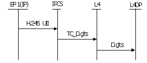
UII Digit Routing
The H.323 Stack passes UII digits to Layer 4 (L4)
The Digit Routing to L4 CH Received in UII (0x06) configuration byte sends a Tone Control (TC_Digit) request to L4, so that the digits will be collected in the L4 Dialing Plan (DP).
The DTMF signal is received in the H.323 in two parts.
• The Signal message will be received as digits either as the default duration or actual duration.
• The optional Signal Update message follows the Signal message to specify the override default duration. The Signal Update message is currently handled in H.323 as a Signal Update event in the H.245 PPL.
When this feature is enabled and the Signal Update message is received the Signal message is ignored.
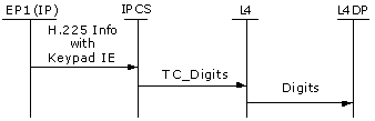
Keypad IE Digit Routing
The CSP routes digits from Keypad IE to Layer 4 (L4)
Currently, the H.323 software does not sense the Keypad IE information when it arrives in the H.225 Information message. This feature provides that the H.225 Information message will be decoded in the H.323 stack. When the message includes a Keypad IE it will be extracted for the digits.
The Enable Digit Routing to L4 CH Received in Keypad IE (0x04) configuration byte allows the H.323 stack to pass the digits collected through the Keypad IE to L4. The Keypad IE information will be extracted and stored if it is available in the message. The digits are decoded in the IE that is being sent and propagated to L4 as if the DSP has received a digit. This in turn will be routed to L4DP.
The H.225 Information message is managed by the H.225 PPL Atomic Function AF 94 which provides for digit processing and routing the digits to L4.
RFC 2833 Digit Routing
The CSP routes digits coming from RFC 2833 to L4
The RFC 2833 is an IETF standard used to transmit digits over VoIP networks such as H.323. This is an In-band method of sending digits within the Real Time Protocol (RTP).
To use RFC 2833, the The IP Network Interface Series 2 card, VoIP modules need to be configured. This VoIP profile can be enabled for the RFC 2833 in the host. The IPCS card queries each VoIP module once, when the first call is sent. This information is stored in H.323 software database for further reference. The H.323 stack will be allowed to route digits from the RFC 2833 to L4.
The Resource Attribute Query (0x00E4) message queries the database using the following TLVs:
• RFC 2833 Enable (0x01E2) TLV indicates whether the RFC 2833 is enabled or not.
• RFC 2833 Dynamic Payload Type (0x01E2) TLV indicates the RFC 2833 payload size.
When enabled RFC 2833 outsiezes the VoIP information along with other parameters.