You are here: CSP Developer’s Guide: Internet Protocol > 8 Routing VoIP Calls > IP Based Routing

Overview
IP Based Routing allows the CSP to separate its physical VoIP resources into resource groups that share a common attribute such as the IP subnet. Previously, all VoIP channels had to act as a single resource pool and assigned connections without regard to the IP address of the media port or remote endpoint. (Throughout this section, "IP media port" refers to either a port on the VDAC-ONE card or IP Network Interface Series 2 card).
With IP Based Routing, you can prevent a situation where a VoIP port, pulled from a common pool, cannot reach an endpoint because it is on the wrong IP subnet.
We recommend that you use two cards, in any of the following combinations:
• Two IP Network Interface Series 2 cards
• Two VDAC-ONE cards
• One IP Network Interface Series 2 card and one VDAC-ONE card
With IP based routing you can control the resources across the two cards to determine how calls come into and out of the CSP.
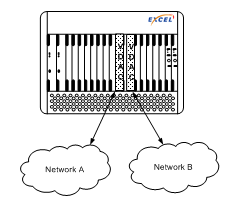
Figure 8-5 Two VDAC Cards
This feature is useful in the carrier environment where different carriers are on different subnets or on different IP networks. You can assign a range of spans to carriers so one carrier does not consume a disproportionate number of available spans.
The following diagram provides an overview of the IP Based Routing process. Each step is explained following the diagram. These steps apply to SIP and H.323 calls and the differences are called out.
Figure 8-6 IP Based Routing Process
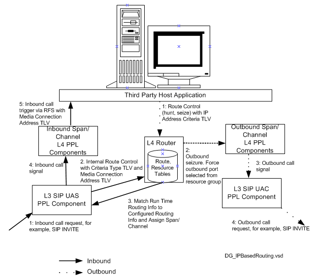
Steps - Inbound
1. For SIP calls, the INVITE message comes into the Layer 3 SIP User Agent Server on the CSP. For H.323, the H.225 Setup message comes into Layer 3.
2. The following TLVs in the VoIP Protocol Configure (0x00EE) message determine how the SIP stack operates. The combination of TLVs depends on which routing method is used.
Method 1
• Routing Method (0x0013)
- Value: Criteria Type 0x0008
• Criteria Type (0x0008)
- Value: 0x2A0E Media Connection Address
• Router Protocol ID (0x000F)
- Value: 0x0B (default)
• Media Connection Address (0x2A0E).
Value automatically added by SIP stack from SDP
Method 2
• Routing Method (0x00013)
-Value: Route Group ID 0x0006
• Route Group ID (0x0006)
- Value: Route Group ID
• Router Protocol ID (0x000F)
- Value: Router Protocol ID
• Criteria Type (0x0008)
- Value: 0x2A0E Media Connection Address
• Media Connection Address (0x2A0E)
Value automatically added by SIP stack from SDP
3. The SIP stack sends the internal Route Control message to the Layer 4 Router component. The message uses the Routing Method of Criteria Type. The criteria type is Media Connection Address. The SIP stack extracts the IP address from the "cline" parameter from the SDP of the INVITE message and automatically puts in the Media Connection Address TLV (0x2A0E).
4. The Router component compares this run time information to the configured routing information. If there is a match, the appropriate resource group is hunted. The router returns a VoIP port with the same subnet to Layer 3.
5. The SIP User Agent Server sends the inbound call signal to the Inbound Span/Channel Layer 4 PPL components.
6. The Layer 4 PPL components send an inbound call trigger to the host application in the Request for Service with Data message. This message can contain the media IP address of the endpoint if the VoIP Protocol Configure (0x00EE) message was sent with the SIP Message Information Mask TLV 0x027F set to include Media Connection Address. For H.323 calls, this TLV is H.323 Message Information Mask TLV (0x02D4). The inbound call is completed.
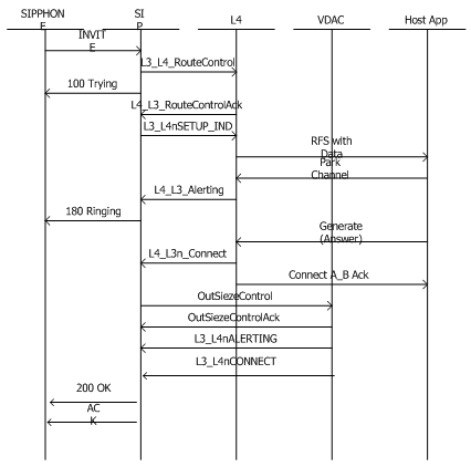
Figure 8-7 Call Flow - Inbound SIP Call
The following call flow diagram shows an inbound SIP call. H.323 calls are essentially the same. Note that the Criteria type is Media Connection Address.
Steps - Outbound
1. The host application sends the Route Control message to the Router component to hunt and seize the outbound resources. The host selects routing information (including subnet) based on a host-based SIP registration database or something similar.
2. The host includes the IP Address Criteria TLV (0x27B4) as the Criteria Type and the IP address that matches the appropriate routing information. The host selects the VoIP port from resource groups that are configured to be on the matching subnet.
3. The Router component sends an outbound seizure to the outbound span/channel Layer 4 PPL components.
4. The Layer 4 PPL components send the outbound call signal to the Layer 3 SIP User Agent Client.
5. The SIP User Agent Client initiates the outbound call using a SIP INVITE message. For H.323 calls, Layer 3 sends a SETUP message.
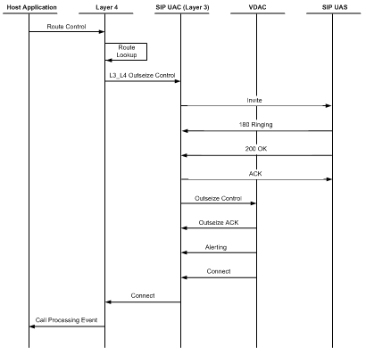
Call Flow - Outbound SIP Call
The following call flow diagram shows an outbound SIP call. H.323 calls are essentially the same.
The following is a sample Route Control message for the outbound side of a call using IP Based Routing.
00 Address Method
01 Number of Address Elements
29 02 ff fe Router AIB - Route Handle FF FE
02 ICB Count
03 ICB Type, Extended
00 1e Generic PPL TLV ICB
00 13 ICB data length
00 03 Number of TLVs
00 13 00 02 00 08 Routing Method = Criteria Type 0x0008
00 08 00 02 27 B4 Criteria Type TLV = Use IP Address
00 0F 00 01 0B Router protocol ID = 0x0b
03 ICB type 03=extended
00 33 NPDI Universal ICB
00 1a ICB Data Length
00 03 Number of TLVs
27 7E 00 03 08 00 00 Remote Side Protocol 08=SIP
27 B4 00 04 IP Address Criteria
27 17 00 05 10 00 04 22 11 Called Party Number
Steps - Inbound
1. The INVITE message comes into the Layer 3 Call Agent Server on the CSP.
2. The SIP stack sends the internal Route Control message to the Layer 4 Router component. Because this call is a call agent call, the CSP does not yet know the IP address.
3. The SIP Call Agent Server sends the inbound call signal to the Inbound Span/Channel Layer 4 PPL components.
4. The Layer 4 PPL components send an inbound call trigger to the host application in the Request for Service with Data message.
5. The host application sends the Connect with Data (0x0005) message which allows the router to couple a virtual channel to a physical IP media channel. The Connect with Data message includes the Criteria Type TLV with the IP Address Criteria 0x27B4 as the routing criteria.
1. The Router component sends an outbound seizure to the outbound span/channel Layer 4 PPL components.
2. The Layer 4 PPL components send the outbound call signal to the Layer 3 SIP Call Agent Client.
3. The SIP Call Agent Client initiates the outbound call using a SIP INVITE message.