You are here: CSP Developer’s Guide: Internet Protocol > 8 Routing VoIP Calls > Routing SIP and H.323 Calls Using Route Control Message
Routing SIP and H.323 Calls Using Route Control Message

Overview
This section explains routing VoIP calls that are controlled by SIP and H.323 where your host application uses the Route Control message to route the outbound side of the call. Using the Route Control message allows the host application to leverage Layer 4 Router functionality thereby relieving the host application from making the span/channel assignments on the IP Network Interface card modules.
The Router component (0x64) is a PPL state machine that references a database of resources (the Route Table) to route calls. It is separated from the call processing logic in the CSP. Refer to RTR Router (0x64) in the Developer’s Guide: Overview for PPL information including configuration bytes and general purpose registers.
A Route Table is a special type of PPL table (Type 3) containing only routing criteria data. The router accesses the table to obtain a destination address or criteria data type (0x08).
Route Table entries are arranged into route groups that include one criteria type.
A Resource Group table is a special type of PPL table (Type 4) containing only Resource Group data. When the Route Table entry data yields a specific Resource Group ID, the router accesses the table to obtain a destination address.
Resource groups include the span/channel and the IP address of the IP Network Interface card.
Use the following API messages to download the Route Tables and Resource Group tables to the CSP with a .cfg file:
• PPL Table Initiate Download message (0x00D5)
• PPL Table Download message (0x00D6)
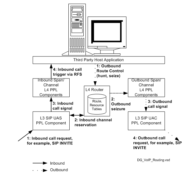
The following diagram shows a call controlled by SIP signaling and identifies each step in the routing process. Each step is further explained after the diagram.
Figure 8-1 Routing Overview - Inbound and Outbound
1. The INVITE message comes into the Layer 3 SIP User Agent Server on the CSP.
2. The SIP stack interfaces with the Router component to reserve the inbound channel.
3. The SIP User Agent Server sends the inbound call signal to the Inbound Span/Channel Layer 4 PPL components.
4. The Layer 4 PPL components send an inbound call trigger to the host application in the Request for Service with Data message. The inbound call is completed.
1. The host application sends the Route Control message to the Router component to hunt and seize the outbound resources.
2. The Router component sends an outbound seizure to the outbound span/channel Layer 4 PPL components.
3. The Layer 4 PPL components send the outbound call signal to the Layer 3 SIP User Agent Client.
4. The SIP User Agent Client initiates the outbound call using a SIP INVITE message.
This section provides examples of how the CSP routes a SIP or H.323 call including:
• A high-level diagram of the CSP Routing
• An example of Route Tables and Resource Groups created using the Converged Services Administrator (CSA) and downloaded to the CSP with the PPL Download message. It is a simplified case in which the CSP has only one VDAC-ONE card with two VoIP modules.
• A Route Control message with the relevant portions annotated
• Detailed steps of how the Route Control message uses the Route Table and Resource groups. These steps refer to specific lines in the Route Table and Resource Group.
• Additional examples of Route Tables and Resource Groups that show the various configurations available. Annotations call out the Resource Groups and the Route Tables.
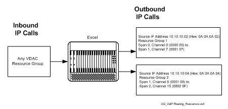
Using Resource Groups
The following diagram shows, at a high level, how both inbound and outbound calls use Resources Groups. The information in this diagram corresponds to the information in the example that follows. That example contains the specific Route Tables and Resource Groups used to configure this scenario.
Following that is the Route Control message as well as the steps that the message completes to select the resources.
Figure 8-2 Resource Groups
One VDAC-ONE Card with Two VoIP Modules
In the following example, two Resource Groups are set up to correspond to the two VoIP modules on the VDAC-ONE card. Annotations are included to make it easier to read.
Route Control Message
The Route Control message uses two or more ICBs to make an outbound SIP or H.323 call. The Generic PPL ICB (0x001E) controls the span-channel and VoIP module selection through the Router component. Below is an example of a Route Control message. The first ICB, which is explained, could be used for a SIP or H.323 call.
00 66 00 e8 00 00 01
00 01 29 02 ff fe - Router AIB - Route Handle FF FE
02 03 00 1e 00 19 - extended ICB with a length of 0x19
00 04 - 4 TLVs to follow
00 13 00 02 00 08 - Routing Method = Criteria Type 0x0008
00 08 00 02 00 65 - Criteria Type TLV = use physical VoIP channel
00 0f 00 01 0b - Router protocol ID = 0x0b
00 65 00 02 00 00 - Physical VoIP Channel
03 00 33 00 37
00 04
29 19 00 08 31 38 37 30 30 30 31 00
29 23 00 0b 42 6f 74 74 6f 6d 2d 43 53 50 00
29 1b 00 0f 31 33 35 2e 31 31 39 2e 35 31 2e 31 38 37 00
27 7e 00 03 08 00 00
How the Route Control Message Uses Route Tables
The following steps explain how the Route Control message uses the Route Tables and Resource Groups to route a call.
1. The AIB (0x29) in the Route Control message directs the call to the Router component.
2. The Routing Method TLV (0x0013) specifies to use a criteria type. The Criteria Type TLV specifies the criteria to use to search for a route.
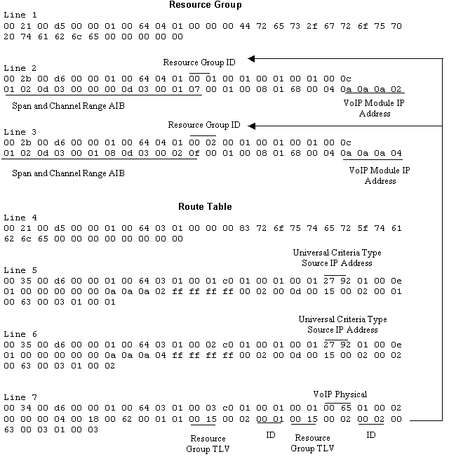
3. The Route Control message directs the Router component to search the Route Table for any resources that are mapped to physical VoIP channels (value - 0x0065 VoIP Physical).
4. The Router component finds Criteria Type 00 65 in Line 7 of the Route Table. Note that Lines 5 and 6 are not matched because they use different criteria types. There are two Terminating Resource Group TLVs (0x0015) in Line 7. The first contains the Resource Group ID 0001 and the second contains Resource Group ID 00002.
5. These IDs map to Resource Group IDs 00 01 and 00 02 respectively in Lines 2 and 3 of the Resource Group.
6. Line 2 maps VoIP Module IP Address 0a 0a 0a 02 to span 0000, channel 00 through span 0001, channel 07. Line 3 maps the VoIP Module IP Address 0a 0a 0a 04 to span 0001, channel 08 through span 0002, channel 0f.
7. The Router component routes the outbound call based on the VoIP module and Span/Channel.
Additional Examples
One VDAC-ONE Card with Four VoIP Modules
Resource Group
00 21 00 d5 00 00 01 00 64 04 01 00 00 00 88 72 65 73 2f 67 72 6f 75 70 20 74 61 62 6c 65 00 00 00 00 00
00 2b 00 d6 00 00 01 00 64 04 01 00 01 00 01 00 01 00 01 00 0c 01 02 0d 03 00 00 00 0d 03 00 01 07 00 01 00 08 01 68 00 04 0a 0a 0a 02
00 2b 00 d6 00 00 01 00 64 04 01 00 02 00 01 00 01 00 01 00 0c 01 02 0d 03 00 01 08 0d 03 00 02 0f 00 01 00 08 01 68 00 04 0a 0a 0a 03
00 2b 00 d6 00 00 01 00 64 04 01 00 03 00 01 00 01 00 01 00 0c 01 02 0d 03 00 02 10 0d 03 00 03 17 00 01 00 08 01 68 00 04 0a 0a 0a 04
00 2b 00 d6 00 00 01 00 64 04 01 00 04 00 01 00 01 00 01 00 0c 01 02 0d 03 00 03 18 0d 03 00 04 1f 00 01 00 08 01 68 00 04 0a 0a 0a 05
Route Table
00 21 00 d5 00 00 01 00 64 03 01 00 00 00 e7 72 6f 75 74 65 72 5f 74 61 62 6c 65 00 00 00 00 00 00 00 00
00 35 00 d6 00 00 01 00 64 03 01 00 01 c0 01 00 01 00 01 27 92 01 00 0e 01 00 00 00 00 00 0a 0a 0a 02 ff ff ff ff 00 02 00 0d 00 15 00 02 00 01 00 63 00 03 01 00 01
00 35 00 d6 00 00 01 00 64 03 01 00 02 c0 01 00 01 00 01 27 92 01 00 0e 01 00 00 00 00 00 0a 0a 0a 03 ff ff ff ff 00 02 00 0d 00 15 00 02 00 02 00 63 00 03 01 00 02
00 35 00 d6 00 00 01 00 64 03 01 00 03 c0 01 00 01 00 01 27 92 01 00 0e 01 00 00 00 00 00 0a 0a 0a 04 ff ff ff ff 00 02 00 0d 00 15 00 02 00 03 00 63 00 03 01 00 03
00 35 00 d6 00 00 01 00 64 03 01 00 04 c0 01 00 01 00 01 27 92 01 00 0e 01 00 00 00 00 00 0a 0a 0a 05 ff ff ff ff 00 02 00 0d 00 15 00 02 00 04 00 63 00 03 01 00 04
00 40 00 d6 00 00 01 00 64 03 01 00 05 c0 01 00 01 00 01 00 65 01 00 02 00 00 00 06 00 24 00 62 00 01 01 00 15 00 02 00 01 00 15 00 02 00 02 00 15 00 02 00 03 00 15 00 02 00 04 00 63 00 03 01 00 05
One Virtual VDAC-ONE Card
Resource Group
00 21 00 d5 00 00 01 00 64 04 01 00 00 00 1a 72 65 73 2f 67 72 6f 75 70 20 74 61 62 6c 65 00 00 00 00 00
00 23 00 d6 00 00 01 00 64 04 01 00 01 00 01 00 01 00 01 00 0c 01 02 0d 03 00 00 00 0d 03 00 1f 1f 00 00 00 00
Route Table
00 21 00 d5 00 00 01 00 64 03 01 00 00 00 25 72 6f 75 74 65 72 5f 74 61 62 6c 65 00 00 00 00 00 00 00 00
00 2e 00 d6 00 00 01 00 64 03 01 00 02 c0 01 00 01 00 01 00 71 01 00 02 00 00 00 03 00 12 00 62 00 01 01 00 15 00 02 00 01 00 63 00 03 01 00 02
Two VDAC-ONE Cards with Four Modules
Resource Group
00 21 00 d5 00 00 01 00 64 04 01 00 00 01 10 72 65 73 2f 67 72 6f 75 70 20 74 61 62 6c 65 00 00 00 00 00
00 2b 00 d6 00 00 01 00 64 04 01 00 01 00 01 00 01 00 01 00 0c 01 02 0d 03 00 00 00 0d 03 00 01 07 00 01 00 08 01 68 00 04 0a 0a 0a 02
00 2b 00 d6 00 00 01 00 64 04 01 00 02 00 01 00 01 00 01 00 0c 01 02 0d 03 00 01 08 0d 03 00 02 0f 00 01 00 08 01 68 00 04 0a 0a 0a 03
00 2b 00 d6 00 00 01 00 64 04 01 00 03 00 01 00 01 00 01 00 0c 01 02 0d 03 00 02 10 0d 03 00 03 17 00 01 00 08 01 68 00 04 0a 0a 0a 04
00 2b 00 d6 00 00 01 00 64 04 01 00 04 00 01 00 01 00 01 00 0c 01 02 0d 03 00 03 18 0d 03 00 04 1f 00 01 00 08 01 68 00 04 0a 0a 0a 05
00 2b 00 d6 00 00 01 00 64 04 01 00 05 00 01 00 01 00 01 00 0c 01 02 0d 03 00 05 00 0d 03 00 06 07 00 01 00 08 01 68 00 04 0a 0a 0a 0b
00 2b 00 d6 00 00 01 00 64 04 01 00 06 00 01 00 01 00 01 00 0c 01 02 0d 03 00 06 08 0d 03 00 07 0f 00 01 00 08 01 68 00 04 0a 0a 0a 0c
00 2b 00 d6 00 00 01 00 64 04 01 00 07 00 01 00 01 00 01 00 0c 01 02 0d 03 00 07 10 0d 03 00 08 17 00 01 00 08 01 68 00 04 0a 0a 0a 0d
00 2b 00 d6 00 00 01 00 64 04 01 00 08 00 01 00 01 00 01 00 0c 01 02 0d 03 00 08 18 0d 03 00 09 1f 00 01 00 08 01 68 00 04 0a 0a 0a 0e
Route Table
00 21 00 d5 00 00 01 00 64 03 01 00 00 01 af 72 6f 75 74 65 72 5f 74 61 62 6c 65 00 00 00 00 00 00 00 00
00 35 00 d6 00 00 01 00 64 03 01 00 01 c0 01 00 01 00 01 27 92 01 00 0e 01 00 00 00 00 00 0a 0a 0a 02 ff ff ff ff 00 02 00 0d 00 15 00 02 00 01 00 63 00 03 01 00 01
00 35 00 d6 00 00 01 00 64 03 01 00 02 c0 01 00 01 00 01 27 92 01 00 0e 01 00 00 00 00 00 0a 0a 0a 03 ff ff ff ff 00 02 00 0d 00 15 00 02 00 02 00 63 00 03 01 00 02
00 35 00 d6 00 00 01 00 64 03 01 00 03 c0 01 00 01 00 01 27 92 01 00 0e 01 00 00 00 00 00 0a 0a 0a 04 ff ff ff ff 00 02 00 0d 00 15 00 02 00 03 00 63 00 03 01 00 03
00 35 00 d6 00 00 01 00 64 03 01 00 04 c0 01 00 01 00 01 27 92 01 00 0e 01 00 00 00 00 00 0a 0a 0a 05 ff ff ff ff 00 02 00 0d 00 15 00 02 00 04 00 63 00 03 01 00 04
00 35 00 d6 00 00 01 00 64 03 01 00 05 c0 01 00 01 00 01 27 92 01 00 0e 01 00 00 00 00 00 0a 0a 0a 0b ff ff ff ff 00 02 00 0d 00 15 00 02 00 05 00 63 00 03 01 00 05
00 35 00 d6 00 00 01 00 64 03 01 00 06 c0 01 00 01 00 01 27 92 01 00 0e 01 00 00 00 00 00 0a 0a 0a 0c ff ff ff ff 00 02 00 0d 00 15 00 02 00 06 00 63 00 03 01 00 06
00 35 00 d6 00 00 01 00 64 03 01 00 07 c0 01 00 01 00 01 27 92 01 00 0e 01 00 00 00 00 00 0a 0a 0a 0d ff ff ff ff 00 02 00 0d 00 15 00 02 00 07 00 63 00 03 01 00 07
00 35 00 d6 00 00 01 00 64 03 01 00 08 c0 01 00 01 00 01 27 92 01 00 0e 01 00 00 00 00 00 0a 0a 0a 0e ff ff ff ff 00 02 00 0d 00 15 00 02 00 08 00 63 00 03 01 00 08
00 58 00 d6 00 00 01 00 64 03 01 00 09 c0 01 00 01 00 01 00 65 01 00 02 00 00 00 0a 00 3c 00 62 00 01 01 00 15 00 02 00 01 00 15 00 02 00 02 00 15 00 02 00 03 00 15 00 02 00 04 00 15 00 02 00 05 00 15 00 02 00 06 00 15 00 02 00 07 00 15 00 02 00 08 00 63 00 03 01 00 09
One IP Network Interface Series 2 Card with Two VoIP Modules
Resource Group
00 21 00 d5 00 00 01 00 64 04 01 00 00 00 44 72 65 73 2f 67 72 6f 75 70 20 74 61 62 6c 65 00 00 00 00 00
00 2b 00 d6 00 00 01 00 64 04 01 00 01 00 01 00 01 00 01 00 0c 01 02 0d 03 00 00 00 0d 03 00 07 1f 00 01 00 08 01 68 00 04 0a 0a 0a 02
00 2b 00 d6 00 00 01 00 64 04 01 00 02 00 01 00 01 00 01 00 0c 01 02 0d 03 00 08 00 0d 03 00 0f 1f 00 01 00 08 01 68 00 04 0a 0a 0a 03
Route Table
00 21 00 d5 00 00 01 00 64 03 01 00 00 00 83 72 6f 75 74 65 72 5f 74 61 62 6c 65 00 00 00 00 00 00 00 00
00 35 00 d6 00 00 01 00 64 03 01 00 01 c0 01 00 01 00 01 27 92 01 00 0e 01 00 00 00 00 00 0a 0a 0a 02 ff ff ff ff 00 02 00 0d 00 15 00 02 00 01 00 63 00 03 01 00 01
00 35 00 d6 00 00 01 00 64 03 01 00 02 c0 01 00 01 00 01 27 92 01 00 0e 01 00 00 00 00 00 0a 0a 0a 03 ff ff ff ff 00 02 00 0d 00 15 00 02 00 02 00 63 00 03 01 00 02
00 34 00 d6 00 00 01 00 64 03 01 00 03 c0 01 00 01 00 01 00 65 01 00 02 00 00 00 04 00 18 00 62 00 01 01 00 15 00 02 00 01 00 15 00 02 00 02 00 63 00 03 01 00 03
Two Virtual IP Network Interface Series 2 Cards
Resource Group
00 21 00 d5 00 00 01 00 64 04 01 00 00 00 34 72 65 73 2f 67 72 6f 75 70 20 74 61 62 6c 65 00 00 00 00 00
00 23 00 d6 00 00 01 00 64 04 01 00 01 00 01 00 01 00 01 00 0c 01 02 0d 03 00 00 00 0d 03 00 1f 1f 00 00 00 00
00 23 00 d6 00 00 01 00 64 04 01 00 02 00 01 00 01 00 01 00 0c 01 02 0d 03 00 32 00 0d 03 00 51 1f 00 00 00 00
Route Table
00 21 00 d5 00 00 01 00 64 03 01 00 00 00 2b 72 6f 75 74 65 72 5f 74 61 62 6c 65 00 00 00 00 00 00 00 00
00 34 00 d6 00 00 01 00 64 03 01 00 02 c0 01 00 01 00 01 00 71 01 00 02 00 00 00 04 00 18 00 62 00 01 01 00 15 00 02 00 01 00 15 00 02 00 02 00 63 00 03 01 00 02