Connecting to station telephones
This topic describes how to connect station telephones or other devices
to a CX 2000C board:
Warning:
 |
Important safety notes for telephony
connections
Allow only qualified
technical personnel to install this board and its associated
telephone wiring. Never install
telephone wiring during a lightning storm. Safety regulations
require that you properly ground the board by connecting the
ground stud on the chassis to a good earth ground. If your site connects
to private lines that leave the building, make sure that external
protection is provided. |
Cabling considerations
When cabling your stations (especially off-premises stations), consider
the following issues:
As the cable length increases, the DC resistance increases.
Most telephones operate correctly if the loop current is at least
20 mA. To maintain this minimum current, the total cable resistance
(the resistance on the tip wire plus the resistance on the ring wire)
must be less than 1500 Ohms over the expected temperature range. When
Telcordia guidelines are followed, the cable length cannot exceed
18,000 feet. If these guidelines are exceeded, the attached device
may not operate properly.
As the cable length increases, the cable presents
an impedance to the audio path. This attenuates the audio signals
in both directions and creates an echo path. Attempting to compensate
for the loss by increasing gain will increase the echo and other noise.
The 18,000 foot cable limit also sets a limit of acceptable audio
quality for traditional telephony services. To improve the frequency
response of the loop, many telephone networks add a device called
loading coils when subscriber loops approach or exceed 18,000 feet.
This can increase the echo.
Telephone networks offer services commonly called
foreign exchange circuits. These should be considered for applications
requiring longer loops.
If any section of the wiring between the board and
connected local telephone lines runs outdoors or between buildings
(buried or above ground), be sure to provide adequate lightning protection.
Warning:
 |
For
lines that run between buildings, you or the approved installer
must provide primary protectors at the building service entrance
point. These can be carbon block or gas discharge protectors,
but solid-state protectors are recommended.
The NMS warranty does not cover damage by lightning or other
electrical discharge. |
NMS recommends 24 AWG (0.6 mm) twisted pair cable for distances over
50 feet (15 meters). The following table lists the recommended cable types
and maximum distances for each:
Cable type |
Recommended maximum distance |
CX 2000C-32-R |
All
other CX 2000C boards |
24 AWG twisted pair |
2000 feet |
18
k feet (1500 Ohms maximum) |
0.6 mm twisted pair |
700 meters |
5.5
km (1500 Ohms maximum) |
Cable connections
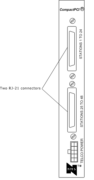
As shown in the following illustration, the station interface connectors
are located on the CX 2000C rear I/O transition board and bracket.
They are RJ-21, 25-pair interfaces.

The connectors are each designed to accommodate a 25-pair cable. This
cable is commonly wired to a punch-down block or break-out box. The telephones
or other station devices are connected to the block or box through standard
telephone wiring as shown in the following illustration:

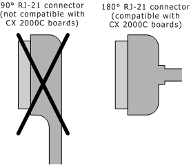
The RJ-21 connector on the cable must be the 180-degree design. The
common 90 degree RJ-21 connector is not compatible with the CX 2000C
board.

The following illustration shows the pin locations for the RJ-21 connectors
on a CX 2000C board:

Connector pinout
The following table describes the pinouts for the top RJ-21 connector
on a CX 2000C (the one labeled STATIONS 1 TO 24):
Station |
Ring
pin |
Tip
pin |
|
Station |
Ring
pin |
Tip
pin |
1 |
1 |
26 |
|
13 |
13 |
38 |
2 |
2 |
27 |
|
14 |
14 |
39 |
3 |
3 |
28 |
|
15 |
15 |
40 |
4 |
4 |
29 |
|
16 |
16 |
41 |
5 |
5 |
30 |
|
17 |
17 |
42 |
6 |
6 |
31 |
|
18 |
18 |
43 |
7 |
7 |
32 |
|
19 |
19 |
44 |
8 |
8 |
33 |
|
20 |
20 |
45 |
9 |
9 |
34 |
|
21 |
21 |
46 |
10 |
10 |
35 |
|
22 |
22 |
47 |
11 |
11 |
36 |
|
23 |
23 |
48 |
12 |
12 |
37 |
|
24 |
24 |
49 |
Note: Pins 25 and 50
are not used.
The following table describes the pinouts for the bottom RJ-21 connector
on a CX 2000C (the one labeled STATIONS 25 TO 48):
Station |
Ring
pin |
Tip
pin |
|
Station |
Ring
pin |
Tip
pin |
25 |
1 |
26 |
|
37 |
13 |
38 |
26 |
2 |
27 |
|
38 |
14 |
39 |
27 |
3 |
28 |
|
39 |
15 |
40 |
28 |
4 |
29 |
|
40 |
16 |
41 |
29 |
5 |
30 |
|
41 |
17 |
42 |
30 |
6 |
31 |
|
42 |
18 |
43 |
31 |
7 |
32 |
|
43 |
19 |
44 |
32 |
8 |
33 |
|
44 |
20 |
45 |
33 |
9 |
34 |
|
45 |
21 |
46 |
34 |
10 |
35 |
|
46 |
22 |
47 |
35 |
11 |
36 |
|
47 |
23 |
48 |
36 |
12 |
37 |
|
48 |
24 |
49 |
Note: Pins 25 and 50
are not used.
Developer's cable kit
NMS provides an optional developer's cable kit. The kit contains two
10 foot RJ-21 cables and two breakout boxes. Each breakout box connects
one RJ-21 to 24 standard RJ-11 (POTS) jacks for individual telephones.
Use the cables to connect to the breakout boxes or to standard 66 or 110
blocks.
All components of the developer's cable kit sold by NMS are also commercially
available from telephone product distributors such as Graybar and Anixter.
These distributors can provide variations in cable lengths.


