RTP loopback connections reverse the direction in which voice data flows when the data reaches an RTP IPv4 or IPv6 endpoint. The data travels through the CG board's IP stack and is looped back at the IP layer so that it can be returned to a DS0 endpoint.
Fusion supports two types of RTP loopback connections:
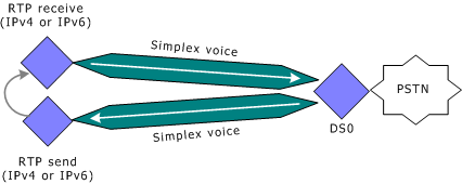
To loop back voice to the originating DS0, two simplex voice channels must be connected to a single DS0 endpoint and two separate RTP (IPv4 or IPv6) simplex endpoints. In this configuration, the application must set the RTP simplex endpoint's local IP address and remote IP address to the same value. The destination UDP port number of the RTP send endpoint must be the same as the receive UDP port number used by the RTP receive endpoint. The IP address used must be a valid address configured for the CG board and must be associated with an active CG board Ethernet interface.
The application connects the RTP simplex send endpoint with a simplex voice channel and a DS0 endpoint. When the data reaches the RTP send endpoint, it is transferred directly back to the RTP simplex receive endpoint. The RTP simplex receive endpoint then transfers the data through a simplex voice channel back to the DS0 endpoint. The following illustration shows an RTP simplex loopback connection:
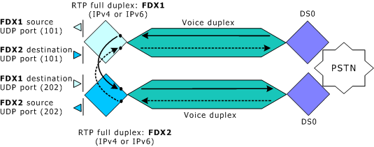
The data from an RTP duplex endpoint cannot be looped back upon itself because this causes SSRC collisions and results in dropped packets. However, applications can loop back full duplex data streams at the CG board Ethernet interface by looping together two full duplex voice connections. Each of these connections consists of an RTP IPv4 or IPv6 full duplex endpoint, a full duplex voice channel, and a DS0 endpoint.
When creating RTP duplex loopback connections, the application creates two full duplex voice connections in which the RTP duplex endpoints use different source UDP port numbers. However, each RTP duplex endpoint uses the other endpoint's source UDP port number as its destination UDP port number. In this way, the configuration loops back the two full duplex data streams between the two connections.
For example, an application can create two duplex voice connections in which one of the RTP duplex endpoints (FDX1 in the illustration below) uses 101 as its source UDP port number and the other RTP duplex endpoint (FDX2 in the illustration below) uses 202 as its source UDP port number. To loop back the data from these connections, the application specifies UDP port 202 as the destination port for endpoint FDX1, and specifies UDP port 101 as the destination port of endpoint FDX2. This configuration directs the full duplex voice data output from FDX1 to the input of FDX2, and vice versa.
The following illustration shows an RTP full duplex loopback connection using two full duplex connections: