You are here: CSP Developer’s Guide: Common Channel Signaling > 2 Introduction to SS7 > Combined Link Set

Overview
The Combined Link Set feature is part of the CSP architecture’s MTP3 layer and supports ANSI and ITU applications. This feature provides the following options:
• The host can configure a combined link set as part of the route configuration, using the SS7 Signaling Route Configure (0x5F) message.
• Load sharing of traffic is possible within the combined link set.
• The 5-bit Signaling Link Selection (SLS) is the default value for the configuration byte (0x0E) in the MTP3 HMRT PPL component (0x2C):
The 5-bit SLS is the default for hierarchical routing to enable backward compatibility with traffic using 32 SLS values to assign to links in a network.
The 8-bit SLS option is not supported in this release.
A route is the combination of one or more link sets used to reach a specific destination. Each link set can belong to more than one route, and contains from 1 to 16 links. A primary route exists for every destination, and represents the fastest path, and least cost, to that destination.
A combined link set establishes the availability of alternate routing configurations that can each serve as a primary path, providing load sharing across the network. Within a combined link set, which can maintain up to a total of 32 links in any combination of link sets, every link is given an equal priority in the routing assignments to the same destination. This means that the more paths that exist to a specific destination in a network, the more reliably messages can be transmitted, even when one or more configured routes fail or experience power outage for any reason.
In the combined link set feature, a routing table tracks the links that have been configured, lists the links that are currently available, and indicates when an update to the network topology is required.
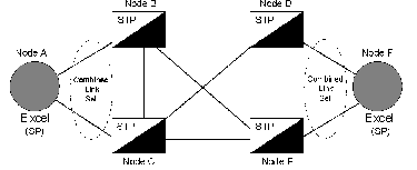
The combined link set will contain links to both Signal Transfer Points (STPs) in an SS7 network that are paired for redundancy and connected to each other by cross links). Refer to the figure below:
Figure 2-14 Combined Link Set Topology
The SLS is the Least Significant Byte (LSB) of the CIC Number, which is found in the routing label of the user part assigned.
If there is only one link set, the LSB serves to identify the link, but the Most Significant Byte (MSB) is not used.
See SS7 Signaling Route Configure (0x5F) in the API Reference for selection of the MSB or LSB values which allow the route to be configured as part of a combined link set.
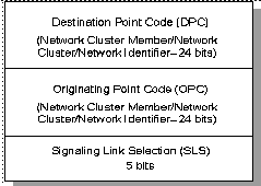
SS7 addressing for nodes, networks, and groups of signaling points in a specific area is done through the use of a point code. A unique 24-bit (three-octet) point code or numeric address is part of the routing label used in the ANSI SS7 MTP3 layer to route the signaling information for a call. This label, which is part of the Signaling Information Field (SIF) of a Message Signal Unity (MSU), contains:
• An 8-bit Destination Point Code (DPC) identifying the termination point
• An 8-bit Originating Point Code (OPC) identifying point of origin for the message.
• A Signaling Link Selection field (SLS) that is used to distribute message traffic over all possible redundant links and routes.
Figure 2-15 Routing Label
Other information about the call, which can include data such as the connection type (bearer capability), carrier identification, and the identification of an unlisted calling number, is also sent as part of the routing label. For the purposes of this document, only the 3-octet point code is relevant.
When the routing function is activated, the DPC is used by a node to select and determine the link set or combined link set for an outgoing message. The network identifier (Network ID) in the DPC directs the message to a particular SS7 network.
The DPC may contain the point code of the next node involved in the transmission route or it can be the final node for the entire route.
Signaling Link Selection (SLS) is used for load sharing when two or more links connect adjacent signaling points. Its function is to distribute the traffic evenly. Each signaling link is assigned an SLS value. This SLS value never changes and identifies the link that the message is routed over. The SLS value must match at both ends of the signaling link.
The SLS is used to select the link within a selected link set to:
• Ensure the sequencing of messages. Any two messages that are sent with the same SLS will always arrive at the destination in the same order in which they were originally sent. That is, if messages are intended to be kept in sequence, the same SLS code will be used so that all such messages take the same path to the destination. For example: a signaling link with ISUP will have the same SLS code used for all messages related to that particular link.
The purpose of the above functionality is to provide the option to reconfigure the signaling network if there are signaling link or signaling point failures, and to control traffic in the event of congestion, blocks or bottlenecks. When a failure occurs, the reconfigurations are carried out so that messages are not lost, duplicated, or placed out of sequence, and excessive message delays are avoided.
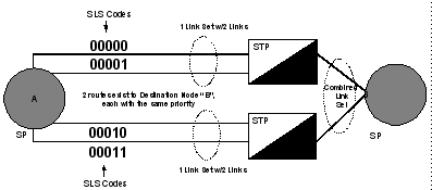
The figures below display the SLS values both for a single link set containing four individual links and a combined link set containing two link sets:
Figure 2-16 Load Sharing within a Single Link Set
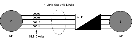
Figure 2-17 Load Sharing in a Combined Link Set
Implementing Combined Link Set
To implement the Combined link set with the 5-bit SLS routing table, the following MTP3 PPL components apply:
TSRC handles the traffic management route control of MTP3; currently it maintains a routing table per destination, and the routing data is kept in the SLS table. This table is updated when a route is added or removed, or when the first MSU is routed for that route.
The SLS table is updated in HMRT to include new routes and all the links of the combined link set, in order to distribute the traffic evenly.
These components are used for the routing functions of changeover and changeback. It is in these components that all necessary changes are made to distribute the traffic based on the normal SLS table. The TSRC component marks the SLS table whenever a new route is added or deleted. This means the table must be updated. Then when an MSU is routed to that destination and the SLS table is already marked with the addition or deletion action, the table will be updated.
All three components--TCBC, TCOC and TSRC--will update the list of available links when required.
When changeover to another route begins, traffic is buffered for that link. All destinations will be marked when that is complete. Then traffic will be sent on alternate links once the changeover ends, and the SLS table will be updated to indicate the new links that are now carrying traffic. Again, this update will only take place when the first MSU is routed.
Changeover diverts traffic from an unavailable link to one or more available links, without message loss, mis-sequencing or duplication.
Important! Traffic is load shared between the two links from the SP to the mated pair of STPs. The STP monitors the error rate. If a link’s functionality deteriorates, the STP will initiate a changeover, thus routing all traffic on to one link. When the faulty link is repaired, the STP will then order a changeback request and traffic is routed back to that link and load sharing is restored.
All destinations are marked when changeback begins, and traffic is re-distributed from alternate links to the link coming up. The SLS table is updated immediately and the alternate links start to buffer traffic. This update occurs, however, only if there is an MSU to be routed to the destination.
Once Changeback is acknowledged by the link coming up, it will buffer the traffic for that alternate link, according to the updated SLS table.
Changeback diverts traffic back to the original route once it becomes available.
Important! A changeover order is always sent over an alternate link, while a changeback order can be routed over any available link.