You are here: CSP Developer’s Guide: Common Channel Signaling > 2 Introduction to SS7 > Configuring SS7 10K Virtual Channels
Configuring SS7 10K Virtual Channels

Overview
The 10K Virtual Channels feature (sometimes referred to as Virtual CICs) allows configuration of virtual T-ONE and E-ONE/J-ONE cards in the CSP. This enhancement meets all standard software requirements for Cantata and does not affect connectivity or performance.
The 10K Virtual Channels feature is supported by the SS7 Series 3 protocol. By configuring virtual channels on the CSP, physical links or voice circuits with their voice and data traffic can be terminated on another switch outside the CSP platform. The CSP simply terminates control channels for the SS7 signaling links and provides management of SS7 Circuit Identification Codes (CICs). No difference is apparent to the CSP between virtual and physical channels installed in the chassis.
Before You Begin
Important! Please note the following:
• A single CSP supports the 10K Virtual Channels feature for this release.
• A maximum of 12,000 T1 or E1/J1 channels can be supported per CSP. There are the 2,000 physical channels and up to 10,000 virtual channels available for licensing (See Licensing of Virtual Channels below.)
• The SS7 Series 3 card supports the 10K Virtual Channels feature.
• The SS7 PQ card does not support the 10K Virtual Channels feature.
• You cannot connect virtual channels over the Exnet Ring. In order for a call to be connected over the Exnet Ring, the channels must be terminated locally (that is, on the CSP or Exnet Connect card).
The licensing of Virtual Channels, based on the CSP chassis serial number, can be from an initial 2,000 up to a maximum of 10,000. To use the 10K Virtual Channels feature, you must configure Virtual Channels in the CSP. The CSP does not distinguish between Virtual Channels and physical channels.
The licensing of Virtual Channels, based on the CSP chassis serial number, can be from an initial 2,000 up to a maximum of 10,000 at 2,000 increments. To enable more than 2000 Virtual Channels you require at least two licenses, one to enable the initial virtual 2000 channels, and a second license to incrementally increase to greater than 2000 Virtual Channels.
The following licensing options are available by model number:
• Initial license for 2,000 Virtual Channels
• Incremental 2,000 Virtual Channels
• Incremental 4,000 Virtual Channels
• Incremental 6,000 Virtual Channels
• Incremental 8,000 Virtual Channels
Activating Licensing of Virtual Channels
To activate any new feature, including 10K Virtual Channels, you must use a Product License Key, which Cantata provides when you purchase the Product License. The key is unique and encrypted.
For details, refer to Downloading License Keys to the CSP in the Licensing Overview chapter in the Developer’s Guide: Overview and the Product License Download message (0x0079) in the API Reference.
Important! If you have two licenses for an upgrade from 2,000 channels to 10,000 channels, use the 10,000 channel license. If you download the 2,000 license after a 10,000 license was already downloaded, the CSP will revert to 2,000 channels.
T-ONE and E-ONE/J-ONE Virtual Cards
Virtual cards function in the same way as physical cards in all respects. Insertion and removal of cards will occur logically for the switch without interruption to service, using the Card Status Query and Card Status Report messages.
Two card types represent the T-ONE and E-ONE/J-ONE virtual cards. These are:
• 0xD2 Virtual T-ONE, 16 span
• 0xD5 Virtual E-ONE/J-ONE, 16 Span
Important! You cannot use Service State Configure to take virtual cards out-of-service.
To support the expanded number of channels, it is necessary to extend the range of slot values for the Virtual Slot Configuration message.
A total of 32 virtual slot values 64-95 (0x40-0x5F) have been added, to allow for the 10k channels to be mapped without the current requirement of mapping a virtual slot to an empty slot in the CSP chassis.
The following tables break down the number virtual cards supported for the additional virtual channels and spans.
Virtual E-ONE/J-ONE Cards: Spans and Channels
|
Channels Licensed |
E-ONE or |
Virtual Channels |
Virtual Spans |
|---|---|---|---|
|
2,000 |
4 |
2,048 |
64 |
|
4,000 |
8 |
4,096 |
128 |
|
6,000 |
12 |
6,144 |
192 |
|
8,000 |
16 |
8,192 |
256 |
|
10,000 |
*20 |
10,080 |
315 |
Important! *The 20th virtual card can only have 11 spans assigned to it to get the maximum of 315 virtual E1/J1 spans allowed.
Virtual T-ONE Cards: Spans and Channels
|
Channels Licensed |
T-ONE Cards |
Virtual Channels |
Virtual Spans |
|---|---|---|---|
|
2,000 |
6 |
2,304 |
96 |
|
4,000 |
11 |
4,224 |
176 |
|
6,000 |
16 |
6,144 |
256 |
|
8,000 |
22 |
8,448 |
352 |
|
10,000 |
*27 |
10,080 |
420 |
Important! *The 27th virtual card can only have 4 spans assigned to it to get the maximum of 420 virtual T1 spans allowed.
A fully configured system provides the following spans, channels and virtual cards at capacity.
Virtual T-ONE and E-ONE/J-ONE Card Span and Channel Capacities
|
Virtual Card Type |
Number of |
Number of |
Number of |
Total Number of Virtual Spans |
Minimum Number of Virtual Cards at Capacity |
|---|---|---|---|---|---|
|
T-ONE (0xD2) |
16 |
24 |
384 |
420 |
27 |
|
E-ONE/J-ONE (0xD5) |
16 |
32 |
512 |
315 |
20 |
Typical Operation of Virtual Spans
The following functions apply to typical operation of the Virtual Spans feature:
• A CSP supports up to 2048 ports and can function with any combination of virtual and physical spans.
• Configuration of virtual spans is done in the same manner as configuration of physical spans.
• Call processing also functions as it would in a CSP system that had only physical spans installed.
• Virtual spans can be configured on local SS7 Server Nodes or on remote nodes.
• Since virtual slots in the switch are each assigned a Card Type as if they were installed as physical cards, both matrix diagnostics and alarms function normally.
• Messaging occurs normally for SS7.
Configuration of Virtual Spans
The Virtual Span configuration sequence incorporates the API messages as shown in the table below:
|
Step |
API Message |
Action |
|---|---|---|
|
1 |
Assign Logical Span ID |
De-assign all of the spans and associated channels in the system. This will remove all virtual slots. These virtual slots must then be configured again. |
|
2 |
Virtual Card Configure |
Add the virtual slots to the system. |
|
3 |
Assign Logical Span ID |
Assign logical spans to the appropriate slots and offsets. |
|
4 |
Messages from Standard Configuration Sequence (SS7) |
See API Developer’s Guide: Overview |
|
5 |
Service State Configure |
Bring all spans and associated channels into service. |
|
6 |
Virtual Span Control |
Inform the switch that the Virtual Spans are operational. (default =non-operational) |
Virtual Card Acts as Physical Card
The Virtual Card Configure message allows the switch to function as if a "real" physical card has been installed. The host receives the Card Status Report as if the virtual card actually existed. It monitors each card type as real (physical) so that the virtual card, whether it is T-ONE or E-ONE/J-ONE, can only be inserted or removed through transmission of the Virtual Card Configure message.
The Virtual Span Control message supervises the actual spans that the virtual card controls. See the API Reference for a detailed description of these messages.
The virtual card addition and the virtual span status is mirrored on the standby matrix. Therefore, in the event of the active matrix failure the standby will take over, maintaining the virtual card and span status. If there are active calls up at the time of the failure, they will still be maintained on the newly active card.
N+1 Redundancy
N+1 redundancy is not a valid redundancy option for a virtual card.
SS7 redundancy mechanisms work exactly the same as they did before, using virtual spans. The only possible implication is that the protocol stacks will query the virtual span state (internal to the system) and will get the latest virtual span status that was configured by the Host via the Virtual Span Control message.
Virtual Spans Example Configuration File
The following is an example configuration file that utilizes the Virtual Card Configure and the Virtual Span Control messages. It sets up two SS7 ANSI stacks and controls CICs on the virtual spans.
The high level CSP configuration is:
Slot 0 SS7 Series 3 card
Slot 1 Virtual 16-span card
Slot 3 T-ONE 16-span card
Spans 0-3 are assigned and carry the signaling links. Spans 0 to 15 are the spans where the CICs are assigned.
'De-Assign all Logical span ids
00 0d 00 a8 00 00 ff 00 01 11 04 ff ff ff ff
'Virtual card configure (add 16 span T1)
'D2 16 Span T1
'D5 16 Span E1/J1
00 0d 00 e0 00 00 FF 00 00 01 01 01 02 01 D2
'Assign logical spans for the links
00 0d 00 a8 00 00 ff 00 01 11 04 00 00 03 00
00 0d 00 a8 00 00 ff 00 01 11 04 00 01 03 01
00 0d 00 a8 00 00 ff 00 01 11 04 00 02 03 02
00 0d 00 a8 00 00 ff 00 01 11 04 00 03 03 03
'Assign spans 8-15 to the virtual slots
00 0d 00 a8 00 00 ff 00 01 11 04 00 08 01 00
00 0d 00 a8 00 00 ff 00 01 11 04 00 09 01 01
00 0d 00 a8 00 00 ff 00 01 11 04 00 0a 01 02
00 0d 00 a8 00 00 ff 00 01 11 04 00 0b 01 03
00 0d 00 a8 00 00 ff 00 01 11 04 00 0c 01 04
00 0d 00 a8 00 00 ff 00 01 11 04 00 0d 01 05
00 0d 00 a8 00 00 ff 00 01 11 04 00 0e 01 06
00 0d 00 a8 00 00 ff 00 01 11 04 00 0f 01 07
'Set span format (ESF, B8ZS, clear channel, 133ft)
00 0d 00 a9 00 00 ff 00 01 0c 02 00 00 52 06
00 0d 00 a9 00 00 ff 00 01 0c 02 00 01 52 06
00 0d 00 a9 00 00 ff 00 01 0c 02 00 02 52 06
00 0d 00 a9 00 00 ff 00 01 0c 02 00 03 52 06
'Set span filter Characteristics (1 second CGA Cleared)
00 0e 00 cd 00 00 ff 00 01 0c 02 00 00 01 00 64
00 0e 00 cd 00 00 ff 00 01 0c 02 00 01 01 00 64
00 0e 00 cd 00 00 ff 00 01 0c 02 00 02 01 00 64
00 0e 00 cd 00 00 ff 00 01 0c 02 00 03 01 00 64
'****************************
'SS7 CONFIGURATION STARTS HERE
'****************************
'-------------------------------------------------------------------------
'Configure First SS7 Stack (A)
'-------------------------------------------------------------------------
'Set Signaling Stack Configure A
'Set our OPC to 00000123 and set the 3 modules to ANSI
00 16 00 5c 00 00 ff 00 01 21 02 00 00 00 00 01 23 03 01 00 02 00 03 00
'Define a Link Set going to 00000987 ID 0
00 0f 00 5d 00 00 ff 00 01 1e 02 00 00 00 00 09 87
'Set the signaling link configuration (SLC 0, Link Id 0, Link Set 0)
00 14 00 5e 00 00 ff 00 02 1f 03 00 00 00 0d 03 00 00 00 00 00 00
'Set the Signaling Route Configure for A
'Define a Route to 00 00 09 87 using only Link Set 0
00 14 00 5f 00 00 ff 00 01 20 05 00 00 00 00 00 00 00 09 87 00 00
' Assign DPC-CIC 00000987=0000-060 for A
00 14 00 6a 00 00 ff 00 01 14 07 00 00 00 00 08 00 18 00 00 09 87
00 14 00 6a 00 00 ff 00 01 14 07 00 00 20 00 09 00 18 00 00 09 87
00 14 00 6a 00 00 ff 00 01 14 07 00 00 40 00 0a 00 18 00 00 09 87
00 14 00 6a 00 00 ff 00 01 14 07 00 00 60 00 0b 00 18 00 00 09 87
'-------------------------------------------------------------------------
' Configure Second SS7 Stack (B)
'-------------------------------------------------------------------------
' Set Signaling Stack Configure B
' Set our OPC to 00000987 and set the 3 modules to ANSI
00 16 00 5c 00 00 ff 00 01 21 02 00 01 00 00 09 87 03 01 00 02 00 03 00
' Define a Link Set going to 00000123 ID 1
00 0f 00 5d 00 00 ff 00 01 1e 02 01 01 00 00 01 23
' Set the Signaling Link Configuration (SLC 0, Link Id 1, Link Set 0)
00 14 00 5e 00 00 ff 00 02 1f 03 01 01 01 0d 03 00 01 00 00 00 00
' Set the Signaling Route Configure for B
' Define a Route to 00 00 01 23 using only Link Set 1
00 14 00 5f 00 00 ff 00 01 20 05 01 00 01 00 01 00 00 01 23 01 00
' Assign DPC-CIC 00000123=0000-0060 for B
00 14 00 6a 00 00 ff 00 01 14 07 01 00 00 00 0c 00 18 00 00 01 23
00 14 00 6a 00 00 ff 00 01 14 07 01 00 20 00 0d 00 18 00 00 01 23
00 14 00 6a 00 00 ff 00 01 14 07 01 00 40 00 0e 00 18 00 00 01 23
00 14 00 6a 00 00 ff 00 01 14 07 01 00 60 00 0f 00 18 00 00 01 23
'****************************
' SS7 CONFIGURATION ENDS HERE
'****************************
'Bring spans into service
00 0c 00 0a 00 00 ff 00 01 0c 02 00 00 f0
00 0c 00 0a 00 00 ff 00 01 0c 02 00 01 f0
00 0c 00 0a 00 00 ff 00 01 0c 02 00 02 f0
00 0c 00 0a 00 00 ff 00 01 0c 02 00 03 f0
'Bring virtual span into service (optional)
00 0c 00 0a 00 00 ff 00 01 0c 02 00 08 f0
00 0c 00 0a 00 00 ff 00 01 0c 02 00 09 f0
00 0c 00 0a 00 00 ff 00 01 0c 02 00 0a f0
00 0c 00 0a 00 00 ff 00 01 0c 02 00 0b f0
00 0c 00 0a 00 00 ff 00 01 0c 02 00 0c f0
00 0c 00 0a 00 00 ff 00 01 0c 02 00 0d f0
00 0c 00 0a 00 00 ff 00 01 0c 02 00 0e f0
00 0c 00 0a 00 00 ff 00 01 0c 02 00 0f f0
'Bring the Links in Service
00 0d 00 0a 00 00 ff 00 01 09 02 00 00 f0 00
00 0d 00 0a 00 00 ff 00 01 09 02 01 01 f0 00
'Bring channels into service
00 12 00 0a 00 00 ff 01 02 0d 03 00 08 00 0d 03 00 08 17 f0
00 12 00 0a 00 00 ff 01 02 0d 03 00 09 00 0d 03 00 09 17 f0
00 12 00 0a 00 00 ff 01 02 0d 03 00 0a 00 0d 03 00 0a 17 f0
00 12 00 0a 00 00 ff 01 02 0d 03 00 0b 00 0d 03 00 0b 17 f0
00 12 00 0a 00 00 ff 01 02 0d 03 00 0c 00 0d 03 00 0c 17 f0
00 12 00 0a 00 00 ff 01 02 0d 03 00 0d 00 0d 03 00 0d 17 f0
00 12 00 0a 00 00 ff 01 02 0d 03 00 0e 00 0d 03 00 0e 17 f0
00 12 00 0a 00 00 ff 01 02 0d 03 00 0f 00 0d 03 00 0f 17 f0
'Virtual Span Control
'Tell the switch the spans are alive
00 0e 00 e2 00 00 FF 00 01 0C 02 00 08 00 01 00
00 0e 00 e2 00 00 FF 00 01 0C 02 00 09 00 01 00
00 0e 00 e2 00 00 FF 00 01 0C 02 00 0a 00 01 00
00 0e 00 e2 00 00 FF 00 01 0C 02 00 0b 00 01 00
00 0e 00 e2 00 00 FF 00 01 0C 02 00 0c 00 01 00
00 0e 00 e2 00 00 FF 00 01 0C 02 00 0d 00 01 00
00 0e 00 e2 00 00 FF 00 01 0C 02 00 0e 00 01 00
00 0e 00 e2 00 00 FF 00 01 0C 02 00 0f 00 01 00
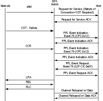
Since virtual T-ONE and E-ONE/J-ONE cards function the same way real cards would in the CSP, the switch will automatically attempt a Continuity Check for a CIC when an IAM is received. The Continuity Check is performed for the voice circuits (CICs). This involves testing whether a tone has been properly transmitted at one end and been received at the other on the CIC for which the call is intended. If the Continuity Check passes, then the call continues. If it does not, the call is released.
However, since no actual span exists, this Continuity Check will fail. To prevent this, the automatic Continuity Check is disabled in the switch. In its place Cantata uses the "Host-controlled Continuity". Using this feature, the host can initiate a Continuity Check manually by choice only.
This section includes call flow examples for Virtual Spans in both ITU and ANSI.
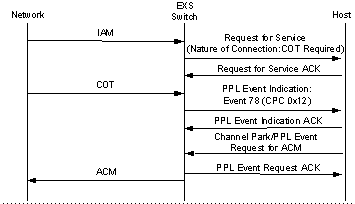
Incoming Call: IAM Received with COT Required
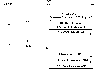
Outgoing Call: IAM Sent with COT Required
This section includes call flow examples for Virtual Spans in ANSI only.
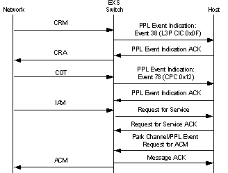
ANSI CRM Received: NOC=COT Required
ANSI CRM Sent: NOC=COT Required

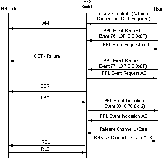
ANSI IAM Sent: COT Failure: Continuity Recheck
ANSI IAM Received: COT Failure: Continuity Re-check