Configuring SS7 Card Redundancy

Purpose
Cantata provides complete redundancy by enabling all interfaces on an SS7 card to be replicated on a standby card when I/O cards are used with two SS7 cards. The I/O card(s) in conjunction with a pair of SS7 cards, prevents the SS7 card from being a single point of failure. A mirror image of the primary card’s signaling configuration is copied to the secondary card. When signaling links are distributed as recommended, if either SS7 card experiences a fault condition, the other card manages all call processing without losing any active calls.
You configure redundancy by using the Redundancy Configure (0x5B) message to designate one SS7 card as primary (active) and the other as secondary (standby) prior to configuring the SS7 interface or after completion of configuration.
Cantata recommends that you send the CCS Redundancy Configure message after resetting the configuration on the whole system. The synchronization of databases on the cards involves intensive processing, so you should send the message when there is little or no call activity on the system. After you send the CCS Redundancy Configure message, all subsequent configuration is distributed to both cards. For example, during an SS7 card switchover, the stable calls remain active and the other calls are purged with the switchover purge code 0x18.
Before You Begin
It is assumed that two SS7 cards and associated I/O card(s) are properly installed. (See the CSP Hardware Installation and Maintenance Guide). Upon power-up, the SS7 cards are automatically brought in service as independent cards.
 Always press the STOP button on the SS7 PQ or SS7 Series 3 line card in a redundant card pair configuration before removing or inserting the corresponding I/O card. For example, in a redundant SS7 PQ or SS7 Series 3 card pair configuration, be aware that the redundant line card may reset when removing or inserting the primary I/O card. If this occurs, the system will lose calls.
Redundancy Architecture
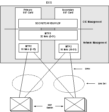
The figure below shows a block diagram of the redundancy architecture and signaling distribution.
Figure 2-8 SS7 Redundancy - Normal Operation
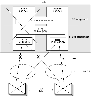
If one of the SS7 cards is reset or faults, the signaling relations between the CSP and remote SS7 CSPs are maintained, as shown in the figure below.
Figure 2-9 SS7 Redundancy - Fault Condition
Configuration
Configure redundancy by designating one SS7 card as the primary card and the other as the secondary card with the CCS Redundancy Configure message. You will receive CCS Redundancy Report messages indicating the status of each card.
Configuring SS7 cards:
Configure signaling stacks and routes on the primary SS7 card. This configuration is automatically transferred to the secondary card during the synchronization process.
The maximum configuration figures for a single card apply to a card pair as well, except for the number of signaling links, which is doubled. Two 16-link SS7 cards support 32 links as a pair.
When the system configures the signaling links, it automatically assigns Link IDs 0–15 to the primary card and Link IDs 16–31 to the secondary card. As long as redundancy is enabled, these Link IDs must be maintained on the respective cards.
To achieve fully fault-tolerant signaling relations, signaling links within a link set should be distributed across the two SS7 cards. In the case of single-link link sets, the signaling routes should be distributed across the SS7 cards.
Constraint
The CCS Redundancy Configure message will fail if the SS7 card in the secondary slot already has any links numbered 0-15 assigned to it. A status of 0xF2 "CCS Redundancy: Not the Primary Slot" returns. Only the SS7 card in the primary slot may have links numbered 0-15 assigned prior to the CCS Redundancy Configure message being sent. The host application must keep track of which SS7 cards currently have links assigned.
Redundancy States
A pair of SS7 cards is in either a synchronization state or a stable state while redundancy is enabled:
Synchronization States
The synchronization states are:
Stable States
The stable states are:
Important! The distinction between States 3 and 4 is transparent to the host. It is for Cantata use only. The SS7 card pair should be in either 3 or 4 during normal operation. In these stable states, both SS7 cards are active and processing calls.
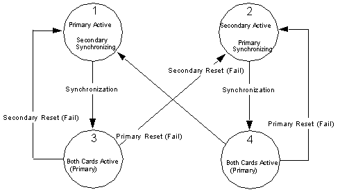
State Transitions
The next figure shows the four states of redundancy and the transition between states due to the resetting of either SS7 card. The host is sent CCS Redundancy Report messages for each of the state transitions shown.
Figure 2-10 Redundancy States