You are here: CSP Developer’s Guide: Internet Protocol > 3 IP Network Interface Series 2 Card > Overview

Introduction
The IP Network Interface Series 2 card is the second generation VoIP line card used in the CSP. In the broadest sense, IP Network Interface Series 2 card is conceptually a VDAC-ONE card with higher channel densities. The IP Network Interface Series 2 card provides an easy migration path for VDAC-ONE users with minimal host impact.
The IP Network Interface Series 2 card performs two-way conversion between circuit-switched data and packet-switched data. This conversion is required by packetized voice applications, such as the Voice over Internet Protocol (VoIP). The card also integrates media resources over IP technology.
Circuit-switched voice is converted to IP packets, using compression algorithms that can increase capacity toward the IP network side. You can have parameters modified for an individual call, often while the call is active, changing the quality of service, as needed.
Integrating media resources using IP technology provides many advantages. Typically, media resources are connected by T1, E1, or J1 interfaces that consume one 64 Kbps port per call, limiting the capacity of the system. The IP Network Interface Series 2 card integrates media resources over IP using the standards-based Real-Time Protocol (RTP).
Integrating media resources using standards-based technology also allows media resources to be shared between the CSP and other network infrastructure. Packet switching to media resources allows the application to benefit from voice compression, increasing capacity on the application. This flexibility allows the CSP and the applications to scale independently and incrementally, as needed, eliminating excess hardware.
Scalability - Single or Dual Modules
Dialogic offers the IP Network Interface Series 2 (IPN-2) card in Single and Dual Module options. These options make the card more cost effective at lower densities, and allow customers flexibility and cost effective redundancy at higher densities, as you pay for only the number of resources you require. You can purchase the IPN-2 card in the following options:
• IP Network Interface Series 2 with One Module – 96 ports that you can upgrade to 256/512 ports (depending on codecs)
• IP Network Interface Series 2 with Two Modules – 192 ports that you can upgrade to 512/1,024 ports (depending on codecs)
• Additional IP ports license are in 96 port increments
Important! If an IPN-2 card fails, its resources are available to the other IPN-2 cards but the host must first transfer those resources to the other cards with the Assign Logical Span (0x00A8) message. See Redundancy for more information on this process.
You download the license to the CSP Matrix Series 3 Card using the Product License Download (0x0079) API message. You query resources with the Product License Query (0x007A) message. The license key type is 0x3131 for both download and query messages. Refer to the License Key ICB 0x24 in the Information Control Blocks chapter.
The ability to license channels frees up more resources for use by the remaining line cards. When the CSP powers up, or when you insert an IP Network Interface Series 2 card, the CSP Matrix Series 3 Card is informed of the module count. This count determines the number of resources added to the resource pool and this count is saved on the CSP Matrix Series 3 Card. This pool of resources can be used by any IPN Series 2 card in the CSP. Therefore, a single IPN Series 2 card may get to use all resources or the resources may be shared among all IPN Series 2 cards.
If you need more resources and download a license to the matrix, the licensed resources are added to the resource pool and the license information is saved in the Software Locked Module table. As you assign logical spans, the resource count is decremented.
As logical spans are de-assigned from IPN Series 2 cards, the resource count is incremented by 32 and the space assigned to that span is freed up. When you remove an IPN Series 2 card, the resource pool is decremented by the unlicensed resources not currently used by that card. For example if the card supplies 96 unlicensed channels and has a single span (32 channels) assigned to it, the resource pool is decremented by 64 when the card is removed. The timeslot occupied by the card is freed up. When a license downloaded to the matrix, its details are sent to the Standby CSP Matrix Series 3 Card.
The IP Network Interface Series 2 card seamlessly integrates into a CSP system, appearing as a traditional circuit-based line card. The VoIP channels are divided into multiple 32 channel spans, allowing the host application to assign logical span IDs to the IP Network Interface Series 2 card just as it would an E-ONE or T-ONE line card.
Important! Span/Channel is bound to an IP Address/Port during call setup. The Route Control/Outseize Control messages are used to initiate the call and bind a Span/Channel to the IP Address/Port. This association lasts for the duration of the call.
The IP Network Interface Series 2 card has its own resources to provide echo cancellation, silence suppression, and detection of fax tones. Multiple IP Network Interface Series 2 cards can populate one node, scale to the full capacity of the CSP, and interoperate with all other CSP cards.
Important! The CSP supports a maximum of four IP Network Interface Series 2 cards per chassis with Profile 2 only. Profile 1 supports a maximum of two cards.
Adding the IP Network Interface Series 2 card to existing enhanced-service platforms allows applications to be quickly IP-enabled, providing a significant advantage over other systems that require developers to rewrite the application for packet transport. The ability to support both circuit- and packet-based transport enables developers to create entirely new services, such as text-to-speech and web-based applications.
The IP Network Interface Series 2 card has the flexibility to configure its VoIP modules to support multiple VoIP resource profiles. A resource profile defines the terminal capabilities of a VoIP endpoint (for example, a VoIP module). A VoIP resource profile’s terminal capabilities consist of:
• The maximum number of VoIP channels supported.
• The list of supported VoIP codecs along with each codec’s base, default and maximum packet rate.
• The maximum size of a channel’s Jitter Buffer.
• The maximum size of a channel’s Echo Canceller Tail Length.
• A list of supported VoIP channel features:
Fax Relay
Digit Relay (RFC 2833)
RTP Redundancy (RFC 2198)
• A list of supported VoIP channel attributes along with their:
Default Value
Range of Valid Values
Whether a module wide default can be set. If not, then the attributes can only be set during call establishment using Route/Outseize Control messages.
Whether its value can be changed for an active call.
The VoIP capabilities of the VDAC-ONE and IP Network Interface Series 2 cards are defined by the resource profiles assigned to each IP endpoint (module). Based on the terminal capabilities of the profile, the host decides how each VoIP channel can best be provisioned. Listed below are the basic profile components. Refer to VoIP Resource Profile Terminal Capabilities for detailed resource profile information.
Important! You cannot mix VoIP resource profiles on the same
IP Network Interface Series 2 card or in the same chassis.
• codecs - G.711 + G.729 A/B + G.723.1 + G.726 + G.727 + T.38 + V.32
• Channels Per Module - 40
• Jitter Buffer Size - 300 milliseconds
• Echo Tail Length - 25 milliseconds
The IP Network Interface Series 2 card supports Resource Profiles 1 and 2.
• codec - G.711 only
• Channels Per Module - 512
• Jitter Buffer Size - 300 milliseconds
• Echo Tail Length - 64 milliseconds
• codecs - G.711 + G.729A/B + G.723.1 + G.726 + T.38
• Channels Per Module - 256
Important! In Profile 2 there are a total of 256 channels. However, one channel is used internally for ICMP support leaving 255 channels.
• Jitter Buffer Size - 300 milliseconds
• Echo Tail Length - 64 milliseconds
For the IP Network Interface Series 2 card, Resource Profile 2 is the default profile. This profile is compatible with the VDAC-ONE default profile (Profile 0). Using the default profile, the IP Network Interface Series 2 card provides 512 vs.160 VDAC-ONE channels. The Resource Attribute Configure (0x00E3) message allows the host to assign a resource profile to a VoIP module.
You can ensure reliability for IP switching at two levels:
• Link Level
• Card Level
Link Level
Each IP Network Interface Series 2 card has three external 100 Mbps Ethernet ports that are configured as a Link Aggregate Group (LAG), extending the effective bandwidth to 300 Mbps. In addition to the increased bandwidth, automatic link failover is provided transparently to the host.
Important! In order to fully utilize the IP Network Interface Series 2 network interface, a Ethernet switch that supports Link Aggregate Groups is required.
Card Level
IP Network Interface Series 2 cards are not hardwired to spans and do not take timeslots from the CSP until they are configured. Card-level redundancy is accomplished with load sharing, where enough capacity is added to keep the system running when one card goes out of service.
Example
In the following example, the IPN-2 card in slot 5 can be considered the "primary" card and the IPN-2 card in slot 6 is the "standby" card. Each card has two modules and use Profile 2.
1. Use the Resource Attribute Configure message to configure slot 5 for Profile 2 and normal (non-gateway) mode.
2. The card in slot 5 takes 16 spans of the 32-channel timeslots from the CSP.
3. Use the Assign Logical Spans message to map the logical spans to the physical spans in slot 5.
4. If slot 5 fails, you take it out of service or physically remove the card from slot 5. The 16 spans of 32 channels are returned to the CSP.
5. Use the Resource Attribute Configure message to configure slot 6 for Profile 2 and normal (non-gateway) mode.
6. The card in slot 6 takes 16 spans of the 32-channel timeslots from the CSP.
7. Use the Assign Logical Spans message to map the logical spans to the physical spans in slot 6.
8. Service resumes using slot 6.
The process is the same for profile 1 or cards with one module. Just the number of spans taken from the CSP differ.
Cost-Effective Service Integration
Adding packet switching capabilities to the already flexible CSP provides many additional cost-saving and revenue-generating benefits. The ability to compress voice increases system capacity toward the IP network side, allowing the same amount of bandwidth to transport voice more cost-effectively, and allowing the excess bandwidth to support more customers. Using packet transport for media resources extends the capacity gains of voice channels to the resource, allowing each service to handle greater call volumes.
Integrating applications through IP provides scalability for the applications because they are no longer limited by the number of interface ports available. The standards-based transport technology allows you to easily add third-party applications. This integration method allows multiple, multi-vendor applications to operate on a single system. Other networks can also share these resources because RTP is a standards-based integration technology.
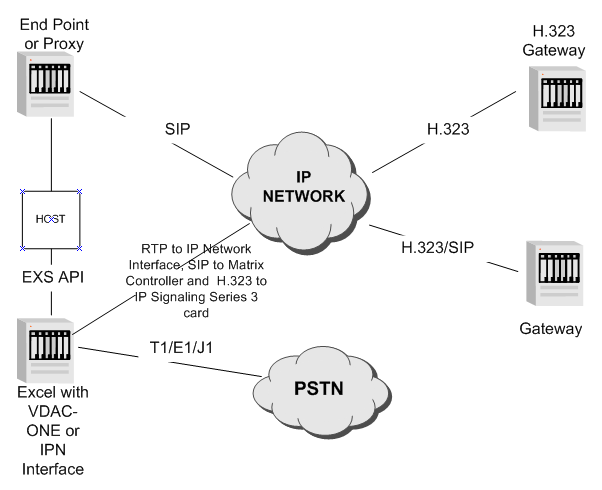
Figure 3-1 Protocol Interworking through the IP Network Interface Series 2 Card
The IP Network Interface Series 2 card supports the following VoIP attributes which can be changed on active (dynamic) codec connections:
• Changing codec voice signals
• Receiving Real Time Protocol (RTP) packets that change codecs dynamically
• Enabling and disabling RTP redundancy
• Changing a codec payload type and payload size during mid call (see below)
The IP Network Interface Series 2 card allows you to dynamically change vocoders during a call.
The host or the signaling protocol sends the following TLVs in the Resource Attribute Configure message (0x00E3) to address the span/channel of the active call.
• RTP Payload Size (0x0101)
• RTP Payload Type (0x0100)
If the payload type or size is out of range, the CSP negatively acknowledges it with a status of 0x5F, Invalid Resource Attribute.
Be sure to specify both the payload type and payload size. If you omit the payload size, the default size for that payload type is used. If you just specify the payload size, leaving the payload type the same, there are potential problems. For example, the far end’s jitter buffer could be almost empty and the change in the packet rate may cause a buffer under run condition.
Transmitted and Received Voice Signals and Packet Rates
The IP Network Interface Series 2 card transmit and receive paths are asymmetrical. This means that the received codec voice signals can be different from the transmitted codec voice signals. This also means that the packet rates can be different. For example, a channel can transmit G.711 at 25 milliseconds and receive G.723.1 at 60 milliseconds.
The maximum packet rates and the base packet rate of each codec is lower for a IP Network Interface Series 2 card than for a VDAC-ONE card. For example, a IP Network Interface Series 2 card supports packet rates from 5 milliseconds to 30 milliseconds in increments of 5 milliseconds for G.711. The VDAC-ONE card supports packet rates from 20 milliseconds to 160 milliseconds in increments of 20 milliseconds for G.711.
Terminal Capabilities of a VoIP Module
The terminal capabilities of a VoIP module can be queried using the Resource Attribute Query (0xE4) message. The VoIP Terminal Capabilities TLV (0x01EA) returns information for a device server to populate its negotiation tables. The IP Network Interface Series 2 and VDAC-ONE cards support this TLV to provide a transparent interface to an external signaling agent.
IP Network Interface Series 2 card Real Time Clock is synchronized with the CSP Matrix Series 3 Card.
Gateway Mode
The IP Network Interface Series 2 card can be configured to either consume physical TDM timeslots or consume extended timeslots. Extended timeslots do not consume any of the chassis physical timeslots, but allow the IP Network Interface Series 2 to come in service. This mode is called Gateway Mode. The IP Network Interface Series 2 card defaults to Gateway Mode. Refer to Gateway Mode.
The default number of IP Network Interface Series 2 cards resources is 96 channels per installed module.You can purchase a license for extra resources in increments of 96 channels as needed.
Media Inactivity Detection (MID) Timer
The Media Inactivity Detection (MID) Timer feature used on the IP Network Interface Series 2 card has been enhanced from the
VDAC-ONE card.
The VDAC-ONE card uses two independent activity timers: the Real Time Protocol (RTP) Timer TLV (0x01EB) and the Media Inactivity Detection (MID) Timer TLV (0x1EC). The RTP Timer monitors a channel’s media stream for the first valid User Datagram Protocol (UDP) packet. The MID Timer monitors a channel’s media stream for any valid Real Time Control Protocol (RTCP) packet. If either of these timers expire, a PPL Event Indication (0x0043) message is generated with the following PPL Events, 0x07 and 0x08 respectively. If, for example, both the RTP Timer and the MID Timer are configured and no valid packets arrive, both PPL events are generated.
IP Network Interface Series 2 Card
The IP Network Interface Series 2 combines the RTP Timer TLV (0x01EB) and the MID Timer TLV (0x1EC) timers into a single Media Inactivity Detection (MID) Timer.
Important! For consistency, the RTP Timer Timeout TLV (0x01EB), for the IP Network Interface Series 2, has been renamed the Initial Media Inactivity Detection (IMID) Timeout Value. The functionality of the IMID remains the same as the RTP Timer.
The feature provides for one MID Timer per channel that monitors activity on the incoming media stream. The host has the ability to specify different timeout values for monitoring the first valid packet versus subsequent packets.
The IP Network Interface Series 2 card MID Timer capabilities are as follows:
• The MID timer is refreshed upon the receipt of any valid UDP packet (for example, RTP and RTCP). The VDAC-ONE card only refreshes its MID timer on valid RTCP packets.
• The MID timer is initialized with the IMID Timeout Value (TLV 0x01EB). If the timer expires before a valid packet is received, a PPL Event Indication (0x0043) message is generated with PPL Event 0x07. Subsequently, when a valid packet is received, the MID timer is reloaded with the MID Timeout Value (TLV 0x01EC). If the timer expired while the MID Timeout Value is loaded, a PPL Event Indication (0x0043) message is generated with PPL Event 0x08.
• If the IMID Timeout Value is set to zero, the MID timer is initialized with the MID Timeout Value.
Important! In order to maintain backwards compatibility with the VDAC-ONE card under this condition, if the MID Timer expires before the first packet is received, a PPL Event Indication (0x0043) message is generated with PPL Event 0x08 instead of PPL Event 0x07.
• The MID Timeout Value can be dynamically updated using the Resource Attribute Configure (0x00E3) message. Updating the MID Timeout Value causes the MID Timer to be re-enabled using this new timeout value.
Important! If the MID Timeout Value is updated while the MID Timer is enabled, the new timeout value is loaded upon receipt of the next valid UDP packet.
• The MID Timer automatically disables itself when the Connection Mode TLV (0x01DB) is changed or not configured to receive packets. The MID Timer is automatically re-enabled when the Connection Mode TLV (0x01DB) is updated to receive packets.
• The MID Timer automatically disables itself when the channel switches to FAX Relay mode. The MID Timer is automatically re-enabled when the channel switches back to Voice Packet mode.
Important! When the MID Timer is automatically re-enabled, the IMID Timeout Value is used, if configured.