You are here: CSP Developer’s Guide: Internet Protocol > 8 Routing VoIP Calls > Routing SIP and H.323 Calls Using Outseize Control Message
Routing SIP and H.323 Calls Using Outseize Control Message

Overview
VoIP applications can use the Outseize Control (0x002C) message for outbound SIP and H.323 signaling. This method is required for application developers who:
• are migrating TDM applications to the VoIP environment if the TDM applications already use the Outseize Control message
• want to control the selection of spans/channels
The host application is responsible for selecting the span and channel for each outbound call on a per call basis. The host application also selects the source IP address and port.
Important! If you do not want the host application to be responsible for the channel management, you can use the Route Control message instead. Refer to Routing SIP and H.323 Calls Using Route Control Message.
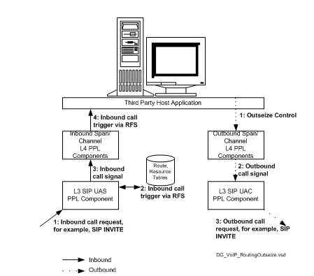
The figure below provides an overview of the routing process. Note that the inbound side of the call is the same as described in the previous section. The outbound side involves the Outseize Control message rather than the Route Control message. The differences are pointed out in the steps following the figure.
Figure 8-3 Routing Process with Outseize Control Message
Steps - Outbound
1. The host application sends the Outseize Control message to the outbound span/channel Layer 4 PPL components. (Note that the Layer 4 Router component is not used.)
The Outseize Control message includes the span/channel, source IP address and port required to route the call. (For details, refer to Sample Outseize Control message following these steps.)
2. The Layer 4 PPL components send the outbound call signal to the Layer 3 SIP User Agent Client.
3. The SIP User Agent Client initiates the outbound call using a SIP INVITE message.
Sample Outseize Control Message
In the following example, the Outseize Control message contains the AIB that specifies the span and channel used to route this call. The NPDI Universal ICB contains six TLVs that specify information about this call as indicated below. You must include the Remote Side Protocol TLV (0x277E) so the call can be handed to the appropriate Layer 3 protocol. For H.323 calls, you must include the IP Signaling Series 3 Card ID TLV (0x27C1) so the call can be delivered to one of the H.323 IP Signaling Series 3 cards in the CSP.
Important! You must use the NPDI TLVs rather than the legacy TLVs for the Outseize Control message to work with SIP and H.323 signaling because they are NPDI-only oriented.
00 40 00 2C 00 00 $node_id
00 - address method
01 - number of address elements
0d - address type = span/channel
03 - data length
00 06 06 - span/channel
01 - number of ICBs to follow
03 - icb type = extended
00 33 - icb subtype
00 2E - icb data length
00 06 - number of TLVs
27 92 00 04 0a 0a 01 25 - Source IP Address
27 93 00 04 00 00 10 80 - Source IP Port
29 19 00 05 33 33 33 33 00 - SIP To Username
27 7E 00 03 08 00 00 - Remote Side Protocol, SIP
27 B0 00 02 01 01 - RTP Payload Type - Egress, G.711 A-Law
27 B1 00 02 01 01 - RTP Payload Size - Egress, 0x01 use Basic Packet Rate
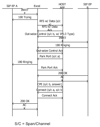
Figure 8-4 Call Flow - VoIP Routing with Outseize Control Message