You are here: PPL Developer’s Guide > 1 PPL Introduction > State Machines

The figure below shows an example of a state machine. The state machine engine drives each channel through its protocol tables based on the occurrence of an event. When a normal state is reached, processing of the event is complete. The dynamic generation of internal blocking states is also supported for service resource requests such as digit receiver allocation.
Figure 1-6 State Machine Example
The current "context" of a component. There are three types of states:
• Normal
• Blocking
• Internal
A normal state can be a wait state (i.e., waiting for a line signaling event, or host input), or a stable state (i.e., conversation state).
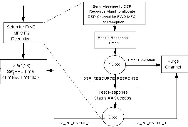
A blocking wait state is automatically generated by the PPL when a "blocking" AF is invoked. A blocking AF is used for allocation of any off-board service resource required by the PPL. Upon the receipt of a positive result of the resource request, the channel "unblocks" and resumes the remainder of the primitive. Blocking is performed on a per object basis without affecting other objects.
Blocking States are transparent to the PPL designer, but they can be tracked in a PPL audit. A blocking state is indicated by 0xFF in the State Status field of PPL Audit Data (see PPL Auditing). This isolates the protocol developer from the details of the internal service management provided by the CSP when creating new PPL protocols. Only normal and internal states can be programmed by the host.
An example of a Blocking state is shown in the figure on the next page.
Figure 1-7 Blocking State
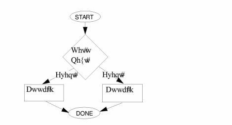
Internal States are used to take a decision branch based upon performing a logical test. An Internal State is initiated by a Test AF, which will result in an internal event being returned based upon the result of the test. Internal states only accept internal events. The documentation for test AFs shows the internal events generated for each result.
The format of an internal state can be represented in standard logic flow chart form, as shown in Logic Flow Chart Decision Branch. The PPL representation of the flow chart as an internal state is shown in the figure on the next page.
Logical Flow Chart Decision Branch
Figure 1-8 Logic Flow Chart Decision Branch
The next page shows a PPL state machine representation of the logic flow chart decision branch above.
PPL State Machine Decision Branch
Figure 1-9 PPL State Machine Representation of Logic Flow Chart Decision Branch
A condition that drives a component out of its current state by invoking an associated primitive, such as:
• Receive Line Signaling Change
Atomic Function (AF)
A predefined, two-argument function that performs a simple protocol action, such as:
• Send Layer 4 Disconnect
The AFs for all default protocols that can be modified using the PPL Composer are documented in the section for each card. They include a description, argument values and ranges, internal events returned for tests, and the minimum software version.
A grouping of one or more AFs and their arguments that allows multiple actions and tests to be initiated in response to a PPL event.