You are here: CSP Developer’s Guide: Common Channel Signaling > 2 Introduction to SS7 > Configuring SS7

Purpose
The table below is a summary of basic SS7 configurations you must perform in addition to the other CSP configurations. A detailed configuration sequence follows this summary.
Before you begin
Acquire the Originating Point Code (OPC) and Adjacent Point Code (APC) before configuring the SS7 stack.
Use the following configuration sequence to bring SS7 signaling links and voice circuits in service. The steps below are used for an SS7 PQ card or SS7 Series 3 card. More details are provided about each step following the table.
|
Step |
Action |
API Message(s) |
|---|---|---|
|
1 |
Assign and configure spans |
|
|
2 |
Configure SS7 license |
Product License Download |
|
3 |
Configure SS7 cards |
CCS Redundancy Configure |
|
4 |
Configure Signaling Stacks |
SS7 Signaling Stack Configure |
|
5 |
Configure Signaling Link Sets |
SS7 Signaling Link Set Configure |
|
6 |
Configure Signaling Links |
SS7 Signaling Link Configure |
|
7 |
Configure Signaling Route(s) |
SS7 Signaling Route Configure |
|
8 |
Assign Voice Circuits (CICs) |
SS7 CIC Configure |
|
9 |
The following entities must be brought in service in this order and messages must sent separately for each: 1. Spans 2. Signaling links 3. CICs |
Service State Configure (This message must be sent for each entity specifying the correct AIB.) |
Assign Logical Span IDs to spans on T1, E1, or J1 line cards you want to use for SS7 with the Assign Logical Span ID message.
Set the span format to Clear Channel by using the T1 Span Configure or E1 Span Configure messages. This step prevents line cards from attempting to extract channel associated signaling from the spans.
Configure SS7 cards in the system as primary or secondary using the CCS Redundancy Configure message. Independent cards are assigned as a primary card. In a redundant pair of cards, one is assigned as the primary card and the other as the secondary.
Subsequent SS7 configuration messages are sent only to primary SS7 cards, which forward the configuration to the secondary card if there is one.
• When configured as a pair, SS7 cards operate in a primary/secondary mode with respect to the call control user part. Signaling links operate in a load-sharing mode.
• Configuration information can be retrieved with the CCS Redundancy Query message.
See Configuring SS7 Card Redundancy for more information.
Example using CCS Redundancy Configure
The following example assigns a single SS7 card as a primary card. See the CCS Redundancy 0x005B message for more details.
Trace: H->X FE 00 0D 00 5B 00 SN NI 00 02 01 01 SA 01 01 SB 00 CS
SN = Sequence Number
NI = Node ID
SA = Slot of first SS7 Card
SB = Slot of second SS7 Card (If there is no second card, this value should be 0xff)
CS = Checksum
Configuring multiple signaling stacks allows the CSP to interface with multiple SS7 networks. Use the SS7 Signaling Stack Configure message to create a stack consisting of three layers: MTP, Call Control User Part (ISUP or TUP), and L3P. If using TUP, you must also configure L3P TUP. Each layer is assigned a variant (ITU-TS or ANSI).
The CSP supports up to four signaling stacks, identified by a Stack ID ranging from 0x00 to 0x03. There is no limitation on how you can allocate SS7 stacks among SS7 cards. For example, you can configure multiple signaling stacks on a single SS7 card or you can configure one signaling stack on each SS7 card, up to a maximum of four stacks per CSP or multi-node system.
Signaling stacks are assigned to SS7 objects (CICs, links, link sets, routes) as each object is configured.
Configuration information can be retrieved with the SS7 Signaling Stack Query message.
Example using SS7 Signaling Stack Configure
The following example sets the OPC of the CSP to 0x111111 and configures all four modules to ITU. See the API Reference for more details on the SS7 Signaling Stack Configure message.
Trace: H->X FE 00 16 00 5C 00 SN FF 00 01 21 02 01 00 00 11 11 11 04 01 01 04 01 03 01 05 01
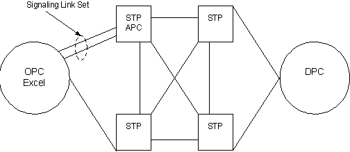
A signaling link set is an abstract path between the CSP and an APC (Adjacent Point Code), to which physical signaling links are added. The same signaling stack must be assigned to all links in a link set. A typical configuration consists of two link sets.
Signaling links in a link set are "load sharing," that is, signaling traffic is distributed equally on the links to optimize efficiency.
When you configure multiple stacks on an SS7 card, the Link Set IDs assigned to each signaling stack must be different. For example, if Link Set ID is assigned to Stack 1, it cannot also be assigned to Stack 2.
However, if you configure multiple signaling stacks on different SS7 cards, the Link Set IDs assigned to the signaling stacks are independent. For example, Link Set ID 1 can be assigned to Stack 1 on one card and Stack 2 on another card.
To assign Link Set IDs, use the SS7 Signaling Link Set Configure API message. Use the SS7 Signaling Link Set Query message to retrieve configuration information.
Example using Signaling Link Set Configure
The following example uses the SS7 Signaling Link Set Configure message to define Link Set 0 going to APC 0x00 0x22 0x33 0x44.
Trace: H->X FE 00 0F 00 5D 00 SN FF 00 01 1E 02 00 00 00 22 33 44
A signaling link is a point-to-point connection between two SS7 point codes (in this case, an CSP and an STP). The SS7 Signaling Link Configure message assigns a physical location in the CSP (timeslot) and a previously configured Signaling Link Set to a signaling link.
Each SS7 card supports either 2, 4, 8, or 16 signaling links depending on which model you purchase. For redundant card pairs, Link IDs 0x00–0x0F must always be assigned to the primary card; Link IDs 0x10–0x1F must always be assigned to the secondary card.
When you configure multiple stacks on an SS7 card, the Link IDs assigned to each signaling stack must be different. For example, if Link ID is assigned to Stack 1, it cannot also be assigned to Stack 2.
However, if you configure multiple signaling stacks on different SS7 cards, the Link IDs assigned to the signaling stacks are independent. For example, Link ID 1 can be assigned to Stack 1 on one card and Stack 2 on another card.
Figure 2-5 Configure Signaling Links
Example using SS7 SIgnaling Link Configure
The following example of the SS7 Signaling Link Configure defines span 1/channel 23 as a signaling link on Link Set 0, using a data rate of 64 Kbps.
Trace: H->X FE 00 14 00 5E 00 SN FF 00 02 1F 03 00 00 00 0D 03 00 01 00 00 00 00
A signaling route defines a path between a signaling stack and a DPC. Each SS7 card supports up to 255 routes, identified by a Route ID ranging from 0x00 to 0xFE. Use the SS7 Signaling Route Configure message to assign the Route IDs.
The SS7 Signaling Route Configure message contains a Destination ID field, which defines the relationship of a signaling stack and a specific DPC. Each SS7 card supports up to 64 distinct Destination IDs
(0x00–0x3F). All routes between a specific signaling stack/DPC pair must use the same Destination ID. Multiple stacks on the same SS7 card must have unique Destination IDs.
When you configure multiple stacks on an SS7 card, the Route IDs assigned to each signaling stack must be different. For example, if Route ID is assigned to Stack 1, it cannot also be assigned to Stack 2.
However, if you configure multiple signaling stacks on different SS7 cards, the Route IDs assigned to the signaling stacks are independent. For example, Route ID 1 can be assigned to Stack 1 on one card and Stack 2 on another card.
Example using SS7 Signaling Route Configure
The following example of the SS7 Signaling Route Configure assigns a route to DPC 0x00 0x33 0x44 0x55. See the API Reference for the format of SS7 Signaling Route Configure.
Trace: H->X FE 00 14 00 5F 00 SN FF 00 01 20 05 00 00 00 00 01 00 33 44 55 00 09
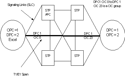
Voice circuits controlled by SS7 Signaling Links are identified by a Circuit Identification Code (CIC). A specific voice circuit is identified in the network by its unique DPC-CIC combination. The SS7 CIC Configure message assigns a DPC/CIC code pair and a User Part (ISUP or TUP) to physical voice circuits. See Configuring Virtual CIC Format for virtual configuration.
• CICs can be assigned to any timeslot in the system.
• CICs in a CIC group must be on the same span.
• CICs and signaling links can reside on the same span.
• Use the SS7 CIC Query message to retrieve configuration information.
Figure 2-6 Assign CICs
Example using SS7 CIC Configure
The following example configures a CIC Group on a T1 span. CIC Group 1 is assigned to span 0, with channel 0 assigned as the base CIC (CIC 0). The remaining channels on the span (1–23) are assigned CIC values 1–23.
Trace: H->X FE 00 15 00 6A 00 SN FF 00 01 14 07 00 01 00 00 18 00 01 02 03 01
Adding CIC Information
This feature is used to add Circuit Identification Code (CIC) information in the Request for Service with Data and Outseize Control messages. The SS7 Address Information data ICB 0x66 defines this information. To enable this feature, on a per channel basis, configuration byte 0x2E of PPL component L3P CIC (0x000F) must be set to 0x01using the PPL Configure message.
Once this feature is enabled, ICB 0x66 provides the addressing information in the Outseize Control message depending on a positive or negative acknowledgement from the Status (MSB, LSB) field. If the Status field indicates a positive acknowledgement (ACK) 0x10, the ICB data is added. Note that the State field is not present. If the Status field indicates a negative acknowledgement (NACK), the ICB data is added after the State field. The State field indicates the state of the call processing channel when a NACK is received.
This feature is backward compatible with earlier releases.
Bring Spans, CICs, and Signaling Links in Service
When all the configuration is complete, use the Service State Configure message to establish a connection with the network and to begin call processing. Upon successful completion, the CSP sends the host a DS0 Status Change message with a status of in service.