This topic describes the following procedures for configuring the CG 6565E board:
The procedures you follow depend on the CG 6565E board configuration you are installing. Configurations with a main board and attached daughterboard provide up to eight T1 or E1 digital trunk interfaces and two Ethernet interfaces. Configurations without a daughterboard provide no trunk interfaces.
Caution: |
The CG 6565E board is shipped in a protective anti-static container. Leave the board in its container until you are ready to install it. Handle the board carefully and hold it only by its handles. Wear an anti-static wrist strap connected to a good earth ground whenever you handle the board. |
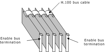
H.100 boards are connected to one another with an H.100 bus cable. The two boards located at either end of the H.100 bus must have bus termination enabled, as shown in the following illustration. Bus termination is controlled by a DIP switch.
The CG 6565E DIP switches are located on the back of the board as shown in the following illustration:
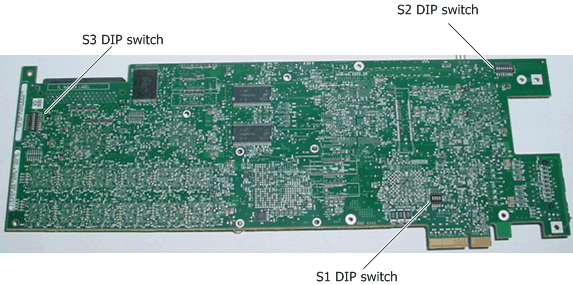
DIP switch |
Description |
S1 |
Sets the mode of the board. Do not modify this setting. Default settings are: Switch 1: on Switch 2: on Switch 3: off Switch 4: on |
S2 |
Sets the mode of the board. Do not modify this setting. Default settings are: Switch 1: on Switch 2: on Switch 3: off Switch 4: off Switch 5: off Switch 6: off Switch 7: off Switch 8: off |
S3 |
Controls the H.100 bus termination. By default, all S3 switches are set to OFF (H.100 bus termination disabled). Setting all S3 switches to ON enables H.100 bus termination. Set all S3 switches to ON only for the boards that are on the ends of the H.100 bus. Note: The switches in the S3 DIP switch must be set to either all ON or all OFF. |
If you are installing a CG 6565E board either without a daughterboard or without configuring the trunk interfaces, be sure that the NetworkInterface.T1E1[x].Type keyword is set to NONE, which is the default.
If the CG 6565E board you are installing has an attached daughterboard, it is shipped to you configured as a T1/E1 120 ohm board. To configure the T1 or E1 interface, make sure the following keywords appear in the board keyword file and perform the following steps:
Step |
Action |
1 |
Set the NetworkInterface.T1E1[x].Type keyword in the board keyword file to T1 or E1. You must configure all trunks that are being used as either T1 or E1. Do not specify more than one trunk type per board. |
2 |
Set the NetworkInterface.T1E1[x].Impedance keyword to one of the following values:
Note: To use E1 75 ohm impedance on the CG 6565E board variant with an MD1 Mini RJ-21 interface, you must use a balun to convert the impedance from 120 ohm to 75 ohm. |
3 |
Set the NetworkInterface.T1E1[x].FrameType, NetworkInterface.T1E1[x].LineCode, and NetworkInterface.T1E1[x].SignalingType keywords to values appropriate for your configuration. |
4 |
Ensure that you use the correct I/O cables. For more information, refer to Cabling a CG 6565E board. |
For more information, refer to CG 6565E board variants.
The following example shows a sample T1 configuration for eight trunks:
NetworkInterface.T1E1[0..7].Type = T1
NetworkInterface.T1E1[0..7].Impedance = DSX1
NetworkInterface.T1E1[0..7].LineCode = B8ZS [other values possible]
NetworkInterface.T1E1[0..7].FrameType = ESF [other values possible]
NetworkInterface.T1E1[0..7].SignalingType = CAS [other values possible]
DSP.C5x[0..47].XLaw = MU_LAW
DSPStream.VoiceIdleCode[0..7] = 0x7F
DSPStream.SignalIdleCode[0..7] = 0x00
The following example shows a sample E1 configuration for eight trunks:
NetworkInterface.T1E1[0..7].Type = E1
NetworkInterface.T1E1[0..7].Impedance = G703_120_OHM
NetworkInterface.T1E1[0..7].LineCode = HDB3 [other values possible]
NetworkInterface.T1E1[0..7].FrameType = CEPT
NetworkInterface.T1E1[0..7].SignalingType = CAS [other values possible]
DSP.C5x[0..47].XLaw = A_LAW
DSPStream.VoiceIdleCode[0..7] = 0xD5
DSPStream.SignalIdleCode[0..7] = 0x09
Note: The syntax [0..7] specifies that the configuration supports any valid number of trunks within the range of 0 through 7 trunks.
Use the CG 6565E daughterboard with the echo chip to provide hardware echo cancellation capabilities and free up DSP resources. When using the hardware echo cancellation capabilities, echo cancellation parameters are fixed. An application cannot change the parameters in the ADI_ECHOCANCEL_PARMS structure with the adiModifyEchoCanceller function.
Use the HardwareEcho.EchoChipEnabled, HardwareEcho.Trunk[x].OnOffTimeslots, and HardwareEcho.XLaw keywords to set hardware echo cancellation.
If the application requires flexibility and you must modify echo cancellation parameters, use DSP resources to provide software echo cancellation capabilities. For more information, refer to the Dialogic® NaturalAccess™ Alliance Device Interface API Developer's Manual.
Note: Do not use both hardware echo cancellation and software echo cancellation at the same time on a CG 6565E board.