Forwards data received from one RTP (IPv4 or IPv6) endpoint to another RTP (IPv4 or IPv6) endpoint.
MSP_FILTER_RTP_SWITCH
MSP_RTP_SWITCHING_CHANNEL_PARMS
Used in simplex switch connections. Applications can create a duplex voice path by connecting RTP IPv4 and IPv6 endpoints with two simplex switch channels. The endpoints must be enabled before the switching channel is enabled. The switching channel must be disabled before disabling the endpoints.
RTP switch filters can be linked to the following endpoint filters:
Input filters |
Output filters |
MSP_ENDPOINT_RTPFDX |
MSP_ENDPOINT_RTPFDX MSP_ENDPOINT_RTPOUT |
MSP_ENDPOINT_RTPIN |
MSP_ENDPOINT_RTPFDX MSP_ENDPOINT_RTPOUT |
MSP_ENDPOINT_RTPFDX_V6 |
MSP_ENDPOINT_RTPFDX_V6 MSP_ENDPOINT_RTPOUT_V6 |
MSP_ENDPOINT_RTPIN_V6 |
MSP_ENDPOINT_RTPFDX_V6 MSP_ENDPOINT_RTPOUT_V6 |
None.
RTP switching filters respond to the following query when the associated channel is connected:
Query ID |
Description |
MSP_QRY_RTPSWITCH_GET_STATE |
Retrieves information about the switch filter state. This information is returned in an msp_FILTER_RTPSWITCH_STATE structure. |
For more information about MSPP service channel initialization and command parameters, refer to the mspcmd.h header file.
The msp_FILTER_RTPSWITCH_STATE query structure is defined as follows:
typedef struct tag_msp_FILTER_RTPSWITCH_STATE{
DWORD FilterId;
DWORD ipFilterState;
DWORD rxDrop;
DWORD rxPkts;
DWORD rxBytes;
DWORD txDrop;
DWORD txFail;
DWORD txPkts;
DWORD txBytes;
}msp_FILTER_RTPSWITCH_STATE;
The msp_FILTER_RTPSWITCH_STATE query structure provides the following information:
Field |
Description |
filter_id |
Reserved. |
IpFilterState |
State of the filter. |
RxDrop |
Number of dropped packets. |
RxPkts |
Number of received packets. |
RxBytes |
Number of received bytes. |
TxDrop |
Number of transmit drop packets. |
TxFail |
Number of failed transmission packets. |
TxPkts |
Number of transmitted packets. |
TxBytes |
Number of transmitted bytes. |
None.
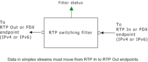
This filter is the only component filter used in a RTP switching channel. RTP switching channels create connections between RTP endpoints so that voice data passes from one endpoint to another in a simplex stream. Applications can create duplex connections by connecting two RTP simplex switch channels to the same RTP endpoint.
When connecting two RTP sessions, consider the following:
At any given time, there should be only one source of voice for the switch channel. That is, if you switch together two RTP endpoints that are both receiving voice from DS0 endpoints, you must disconnect one of the RTP endpoints from its associated DS0 endpoint. Otherwise, each RTP endpoint simultaneously receives voice data from two network sources.
All RTP endpoints switched together using RTP switching channels must use the same encoding/decoding algorithm to process voice data. The RTP switching filter only forwards the packets from one RTP endpoint to another - it does not translate the data from one format to another.
Each RTP endpoint can be connected to a maximum of 32 RTP switching channels.
When applications connect both an RTP switching channel and a duplex voice channel to the same RTP and DS0 endpoint, they must connect the duplex voice channel to the RTP endpoint first. RTP endpoints can support more than one RTP switching connection but can only support one full duplex voice connection (whether the connection consists of a single duplex voice channel or two simplex voice channels).
The following illustration shows an RTP switching filter:
RTP IPv4 full duplex, RTP IPv4 simplex receive, RTP Ipv4 simplex send, RTP IPv6 full duplex, RTP IPv6 simplex receive, RTP IPv6 simplex send